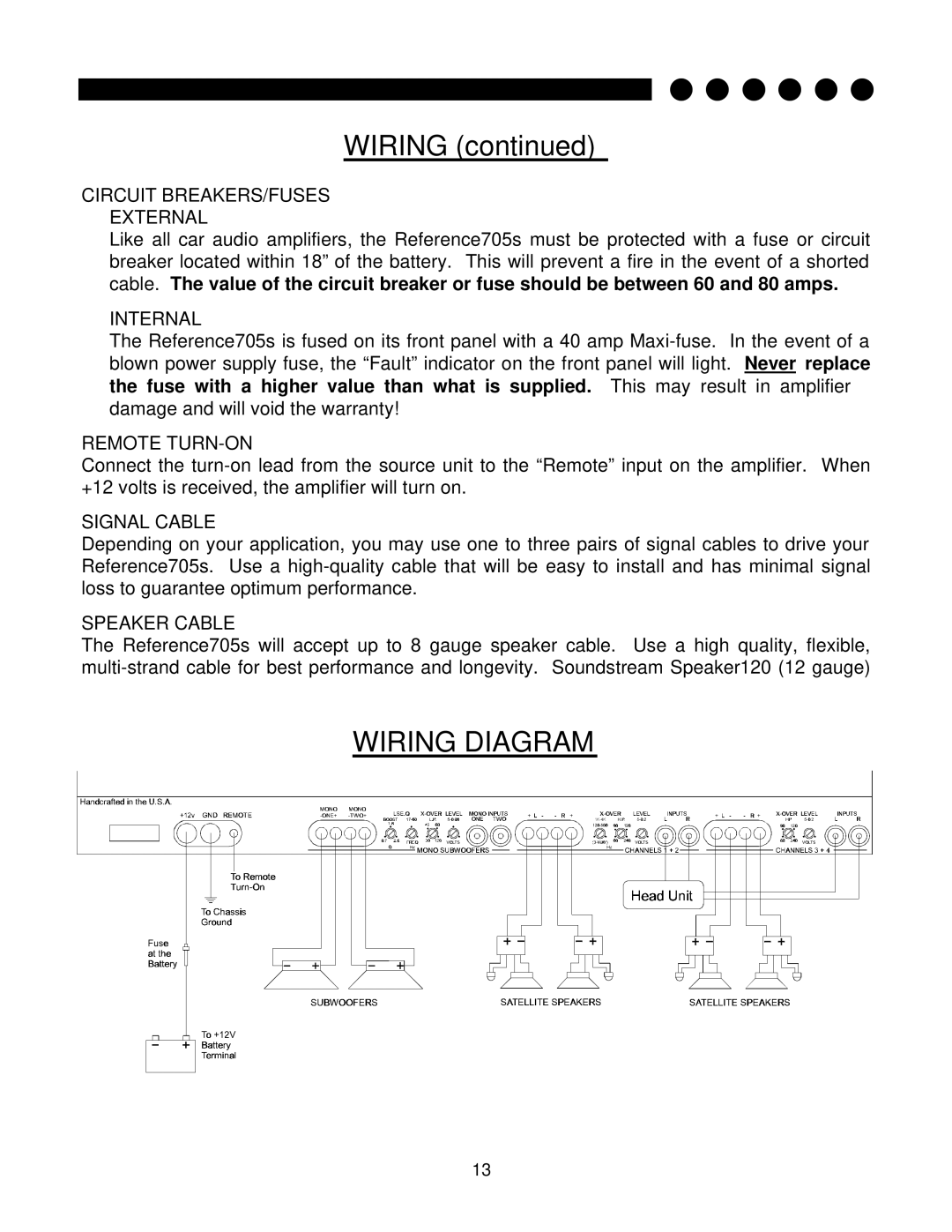
705s specifications
Soundstream Technologies 705s is a standout model in the realm of audio equipment, designed to deliver high-quality sound with a blend of innovative technologies and exceptional characteristics. This model is particularly appealing to audiophiles and casual listeners alike, as it offers an outstanding balance of performance and usability.One of the primary features of the Soundstream Technologies 705s is its versatile audio performance. The system is engineered to reproduce a wide frequency range, ensuring that both low bass notes and crisp high frequencies are delivered with clarity and precision. This broad frequency response is critical for various audio genres, allowing music enthusiasts to experience their favorite tracks as intended by the artists.
Another notable characteristic is the incorporation of advanced digital signal processing (DSP) technology. This feature optimizes sound output by fine-tuning the audio signal in real time, allowing for adjustments that enhance overall sound quality. The DSP technology in the 705s is designed to eliminate unwanted noise and distortion, delivering a clean and immersive listening experience.
In terms of connectivity, the Soundstream Technologies 705s offers multiple input options, including Bluetooth compatibility. This allows users to easily connect their smartphones, tablets, or any Bluetooth-enabled device for seamless streaming. Additionally, the system may include auxiliary inputs and USB ports, enhancing flexibility for all types of audio devices.
The build quality of the 705s is another highlight. Constructed with durable materials, the system is designed to withstand everyday use while maintaining its aesthetic appeal. This rugged yet stylish design makes it suitable for various environments, whether in a home theater setup or as part of a mobile audio system.
Furthermore, the Soundstream Technologies 705s often features adjustable equalizer settings, giving users control over the audio output tailored to their preferences. This customization capability enables music lovers to enhance specific frequencies that resonate with their style, resulting in a perfectly tailored listening experience.
In conclusion, the Soundstream Technologies 705s stands out in the competitive audio market thanks to its rich features, state-of-the-art technologies, and user-centric characteristics. Its powerful performance, connectivity options, and customizable settings make it a top choice for anyone seeking an enriching audio experience. Whether for casual listening or immersive gaming, the 705s delivers consistently exceptional sound performance that is hard to match.

