INSTALLATION
1. PLAN THE INSTALLATION
Before you go any further with the installation of the amplifier, map out the system and the necessary wiring. Your work will be simplified if you have a plan of attack. Consider all electrical requirements, as well as physical, such as amplifier ventilation and availability of space.
2. SELECT OPERATING MODES (on underside)
The configuration switches are accessible by removing the plugs on the underside of the amplifier. They allow you to determine the operating configuration of the amplifier, including:
0 5 or 3 channels of input (via bridging)
0normal (High Power) or low impedance (High Current) operation with the subwoofer channel
0 number of channels of input to drive the amplifier
0 crossover activation for the subwoofer, front, and rear channels
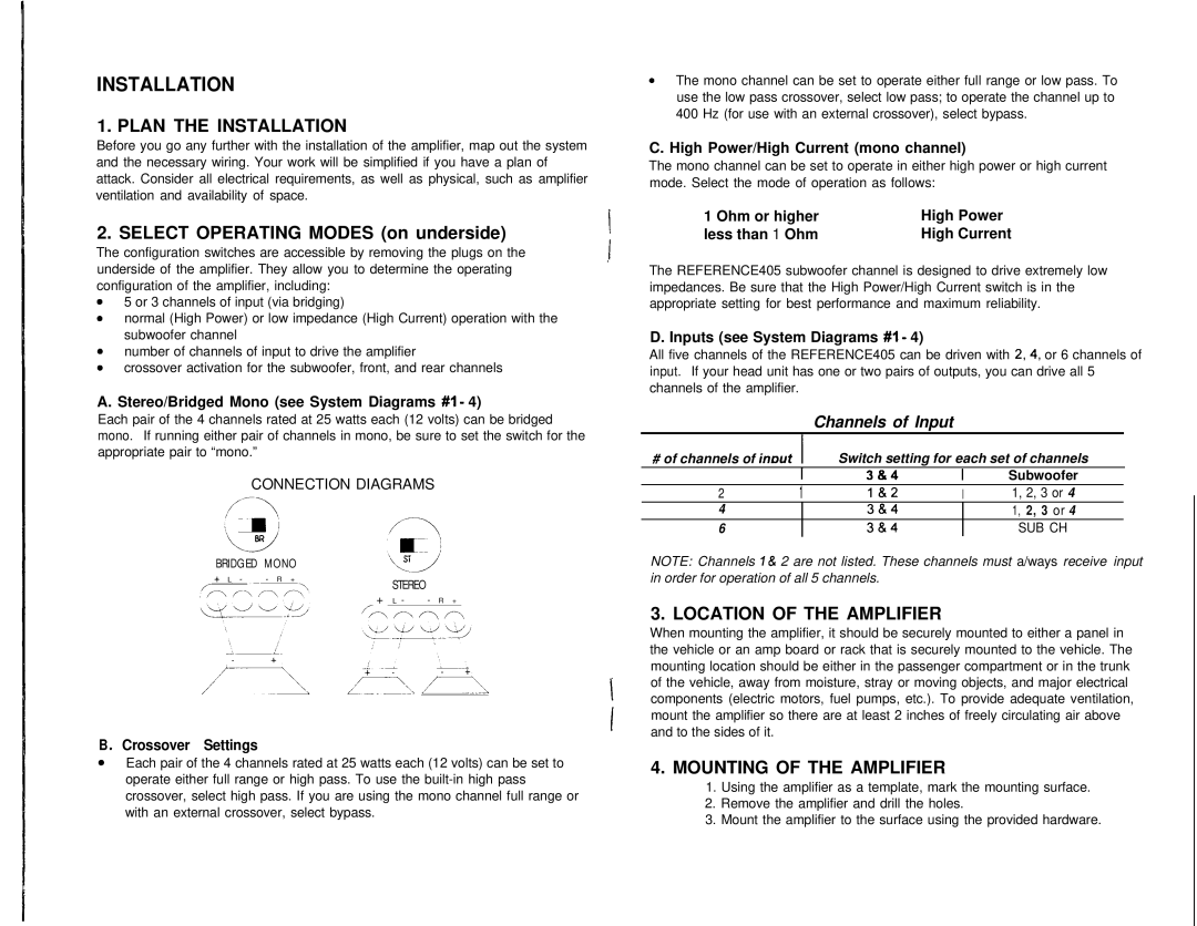
A. Stereo/Bridged Mono (see System Diagrams #1 - 4)
Each pair of the 4 channels rated at 25 watts each (12 volts) can be bridged mono. If running either pair of channels in mono, be sure to set the switch for the appropriate pair to “mono.”
CONNECTION DIAGRAMS
BRIDGED MONO
+ L - | - R + |
| STEREO | |
|
|
| ||
|
|
| + L - - R + |
|
|
| r/m r\ m ,m | ||
B . Crossover Settings
aEach pair of the 4 channels rated at 25 watts each (12 volts) can be set to operate either full range or high pass. To use the
0The mono channel can be set to operate either full range or low pass. To use the low pass crossover, select low pass; to operate the channel up to 400 Hz (for use with an external crossover), select bypass.
C. High Power/High Current (mono channel)
The mono channel can be set to operate in either high power or high current mode. Select the mode of operation as follows:
1 Ohm or higher | High Power |
less than 1 Ohm | High Current |
The REFERENCE405 subwoofer channel is designed to drive extremely low impedances. Be sure that the High Power/High Current switch is in the appropriate setting for best performance and maximum reliability.
D. Inputs (see System Diagrams #I - 4)
All five channels of the REFERENCE405 can be driven with 2,4, or 6 channels of input. If your head unit has one or two pairs of outputs, you can drive all 5 channels of the amplifier.
Channels of Input
# of channels of imut ![]() I Switch setting for each set of channels
I Switch setting for each set of channels
|
| I | 3&4 | I | Subwoofer | ||
2 | 1 |
| l&2 | I | 1, 2, 3 or 4 |
| |
| 4 |
|
| 3&4 |
| 1, 2, 3 or 4 |
|
6 |
|
| 3&4 |
| SUB CH |
| |
NOTE: Channels I & 2 are not listed. These channels must a/ways receive input in order for operation of all 5 channels.
3. LOCATION OF THE AMPLIFIER
When mounting the amplifier, it should be securely mounted to either a panel in the vehicle or an amp board or rack that is securely mounted to the vehicle. The mounting location should be either in the passenger compartment or in the trunk of the vehicle, away from moisture, stray or moving objects, and major electrical components (electric motors, fuel pumps, etc.). To provide adequate ventilation, mount the amplifier so there are at least 2 inches of freely circulating air above and to the sides of it.
4.MOUNTING OF THE AMPLIFIER
1.Using the amplifier as a template, mark the mounting surface.
2.Remove the amplifier and drill the holes.
3.Mount the amplifier to the surface using the provided hardware.