Mfg. Since 5/10 | I N S T R U C T I O N S | Model SB1231 |
Care & Maintenance
d |
!
Always disconnect machine from power before performing maintenance or serious personal injury may result.
| a |
b | e |
For optimum performance from your chuck, follow the maintenance schedule below. Never hammer on the chuck, jaws, or a workpiece that is clamped in the chuck; and never subject the chuck to abrasives, flame, or water.
d |
c Set screw |
Jaw screw retaining pin |
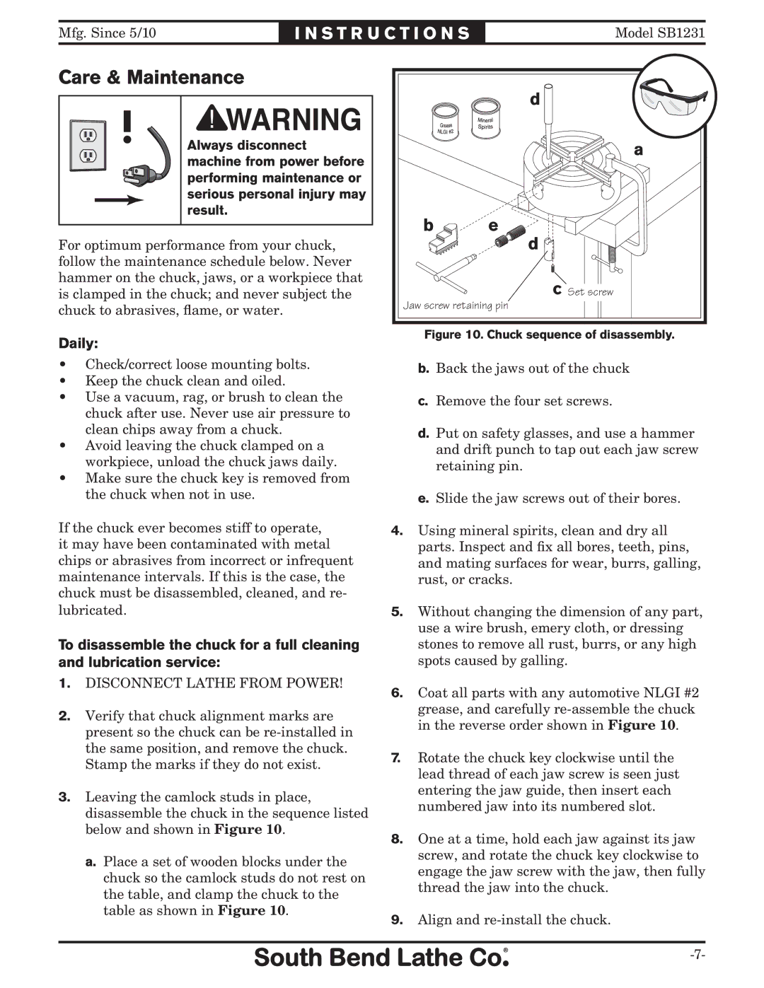
Daily: | Figure 10. Chuck sequence of disassembly. |
|
•Check/correct loose mounting bolts.
•Keep the chuck clean and oiled.
•Use a vacuum, rag, or brush to clean the chuck after use. Never use air pressure to clean chips away from a chuck.
•Avoid leaving the chuck clamped on a workpiece, unload the chuck jaws daily.
•Make sure the chuck key is removed from the chuck when not in use.
If the chuck ever becomes stiff to operate, it may have been contaminated with metal chips or abrasives from incorrect or infrequent maintenance intervals. If this is the case, the chuck must be disassembled, cleaned, and re-
b.Back the jaws out of the chuck
c.Remove the four set screws.
d.Put on safety glasses, and use a hammer and drift punch to tap out each jaw screw retaining pin.
e.Slide the jaw screws out of their bores.
4.Using mineral spirits, clean and dry all parts. Inspect and fix all bores, teeth, pins, and mating surfaces for wear, burrs, galling, rust, or cracks.
lubricated.
To disassemble the chuck for a full cleaning and lubrication service:
1.DISCONNECT LATHE FROM POWER!
2.Verify that chuck alignment marks are present so the chuck can be
3.Leaving the camlock studs in place, disassemble the chuck in the sequence listed below and shown in Figure 10.
a.Place a set of wooden blocks under the chuck so the camlock studs do not rest on the table, and clamp the chuck to the table as shown in Figure 10.
5.Without changing the dimension of any part, use a wire brush, emery cloth, or dressing stones to remove all rust, burrs, or any high spots caused by galling.
6.Coat all parts with any automotive NLGI #2 grease, and carefully
7.Rotate the chuck key clockwise until the lead thread of each jaw screw is seen just entering the jaw guide, then insert each numbered jaw into its numbered slot.
8.One at a time, hold each jaw against its jaw screw, and rotate the chuck key clockwise to engage the jaw screw with the jaw, then fully thread the jaw into the chuck.