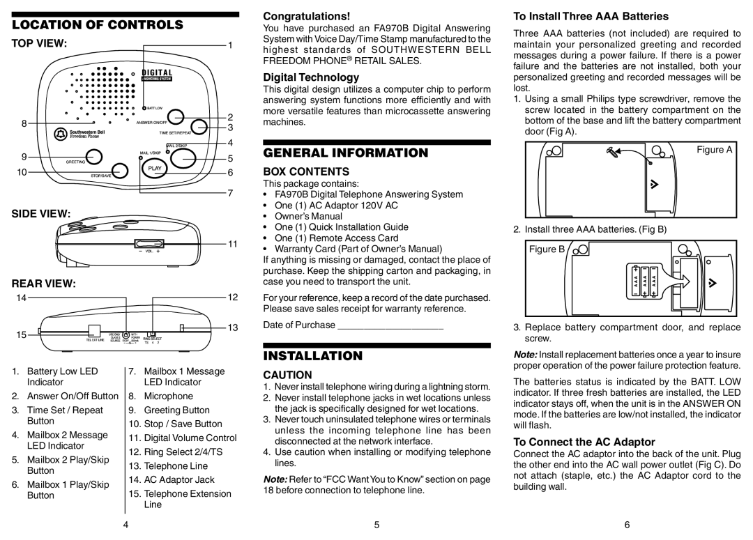
LOCATION OF CONTROLS
Congratulations!
You have purchased an FA970B Digital Answering System with Voice Day/Time Stamp manufactured to the
To Install Three AAA Batteries
Three AAA batteries (not included) are required to
TOP VIEW:
8
9
10
SIDE VIEW:
1 |
2 |
3 |
4 |
5 |
6 |
7 |
11 |
highest standards of SOUTHWESTERN BELL FREEDOM PHONE® RETAIL SALES.
Digital Technology
This digital design utilizes a computer chip to perform answering system functions more efficiently and with more versatile features than microcassette answering machines.
GENERAL INFORMATION
BOX CONTENTS
This package contains:
•FA970B Digital Telephone Answering System
•One (1) AC Adaptor 120V AC
•Owner’s Manual
•One (1) Quick Installation Guide
•One (1) Remote Access Card
•Warranty Card (Part of Owner’s Manual)
maintain your personalized greeting and recorded messages during a power failure. If there is a power failure and the batteries are not installed, both your personalized greeting and recorded messages will be lost.
1.Using a small Philips type screwdriver, remove the screw located in the battery compartment on the bottom of the base and lift the battery compartment door (Fig A).
Figure A
2. Install three AAA batteries. (Fig B)
REAR VIEW:
If anything is missing or damaged, contact the place of purchase. Keep the shipping carton and packaging, in case you need to transport the unit.
14 | 12 | For your reference, keep a record of the date purchased. |
|
| Please save sales receipt for warranty reference. |
15 | 13 | Date of Purchase ____________________ |
|
|
3.Replace battery compartment door, and replace screw.
1. | Battery Low LED |
| 7. | Mailbox 1 Message |
| Indicator |
|
| LED Indicator |
2. | Answer On/Off Button |
| 8. | Microphone |
3. | Time Set / Repeat |
| 9. | Greeting Button |
| Button |
| 10. | Stop / Save Button |
|
|
| ||
4. | Mailbox 2 Message |
| 11. | Digital Volume Control |
| LED Indicator |
| ||
|
| 12. | Ring Select 2/4/TS | |
5. | Mailbox 2 Play/Skip |
| ||
| 13. | Telephone Line | ||
| Button |
| ||
|
| 14. AC Adaptor Jack | ||
6. | Mailbox 1 Play/Skip |
| ||
| 15. | Telephone Extension | ||
| Button |
| ||
|
|
|
| Line |
|
| 4 |
| |
INSTALLATION
CAUTION
1.Never install telephone wiring during a lightning storm.
2.Never install telephone jacks in wet locations unless the jack is specifically designed for wet locations.
3.Never touch uninsulated telephone wires or terminals unless the incoming telephone line has been disconnected at the network interface.
4.Use caution when installing or modifying telephone lines.
Note: Refer to “FCC WantYou to Know” section on page 18 before connection to telephone line.
5
Note: Install replacement batteries once a year to insure proper operation of the power failure protection feature.
The batteries status is indicated by the BATT. LOW indicator. If three fresh batteries are installed, the LED indicator stays off, when the unit is in the ANSWER ON mode. If the batteries are low/not installed, the indicator will flash.
To Connect the AC Adaptor
Connect the AC adaptor into the back of the unit. Plug the other end into the AC wall power outlet (Fig C). Do not attach (staple, etc.) the AC Adaptor cord to the building wall.
6
