
SY-KT333 specifications
The SOYO SY-KT333 is a motherboard that was designed to cater to the needs of both mainstream and enthusiast users during the early 2000s. Targeting the AMD Athlon and Duron processors, this board capitalized on the performance advancements of the time, supporting the Socket A (also known as Socket 462) architecture, and taking full advantage of the VIA KT333 chipset.One of the main features of the SY-KT333 is its impressive memory support. The motherboard can accommodate up to 1.5 GB of DDR SDRAM, which was a considerable amount during its peak usage. With support for DDR266 and DDR333 memory, it offered users the flexibility to utilize high-speed memory modules, enhancing overall system performance. Additionally, the motherboard supports dual-channel mode, allowing for increased bandwidth when two memory sticks are used in tandem.
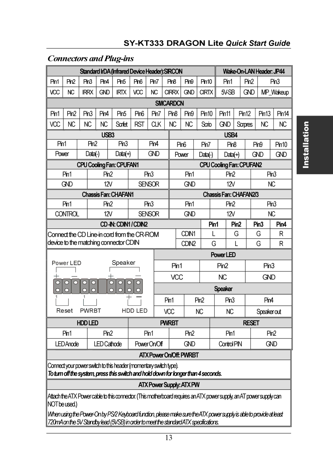
Another significant technology embedded in the SOYO SY-KT333 is its implementation of a 333 MHz Front Side Bus (FSB). This allowed for improved data transfer rates between the CPU and the memory, making it an attractive option for gamers and power users who demanded efficient performance. The SY-KT333 was equipped with a VIA VT8233 Southbridge chip, which provided IDE RAID support, delivering advanced storage solutions for users looking for enhanced data management.
Moreover, the SY-KT333 featured a rich array of expansion slots, including five PCI slots and one AGP 4x slot. This allowed users to expand their systems with additional cards, such as sound cards, graphics cards, and network interfaces, making it suitable for various applications from general computing to gaming. The AGP 4x slot was particularly appealing at the time, offering compatibility with a wide range of graphics cards that could leverage the faster bus for enhanced graphical output.
The onboard I/O capabilities of the SY-KT333 are noteworthy as well, featuring support for 6 USB 1.1 ports, an onboard 10/100 Ethernet controller, and standard audio outputs. This variety of connectivity options made it easy for users to connect peripherals and enjoy multimedia experiences without needing multiple expansion cards.
With its combination of cutting-edge technologies and robust features, the SOYO SY-KT333 offered an appealing solution for those looking to build a powerful AMD-based system in its era. Its ability to support newer components, coupled with its user-friendly design and expandability, made it a notable choice among enthusiasts and general users alike.