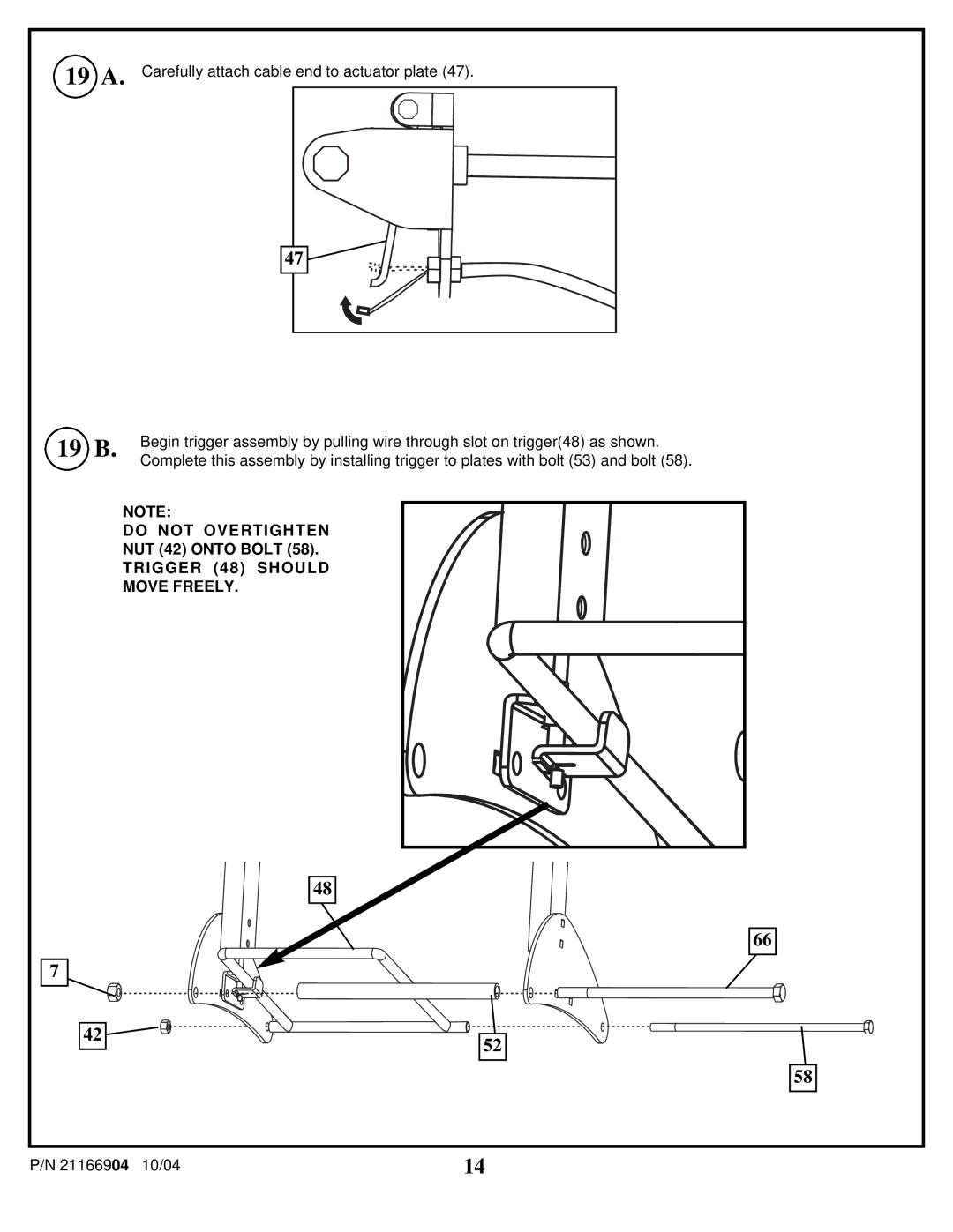
19A. Carefully attach cable end to actuator plate (47).
47
19 B.
7
42
Begin trigger assembly by pulling wire through slot on trigger(48) as shown. Complete this assembly by installing trigger to plates with bolt (53) and bolt (58).
NOTE:
DO NOT OVERTIGHTEN
NUT (42) ONTO BOLT (58).
TRIGGER (48) SHOULD
MOVE FREELY.
48
66
52
58
P/N 21166904 10/04 | 14 |
