
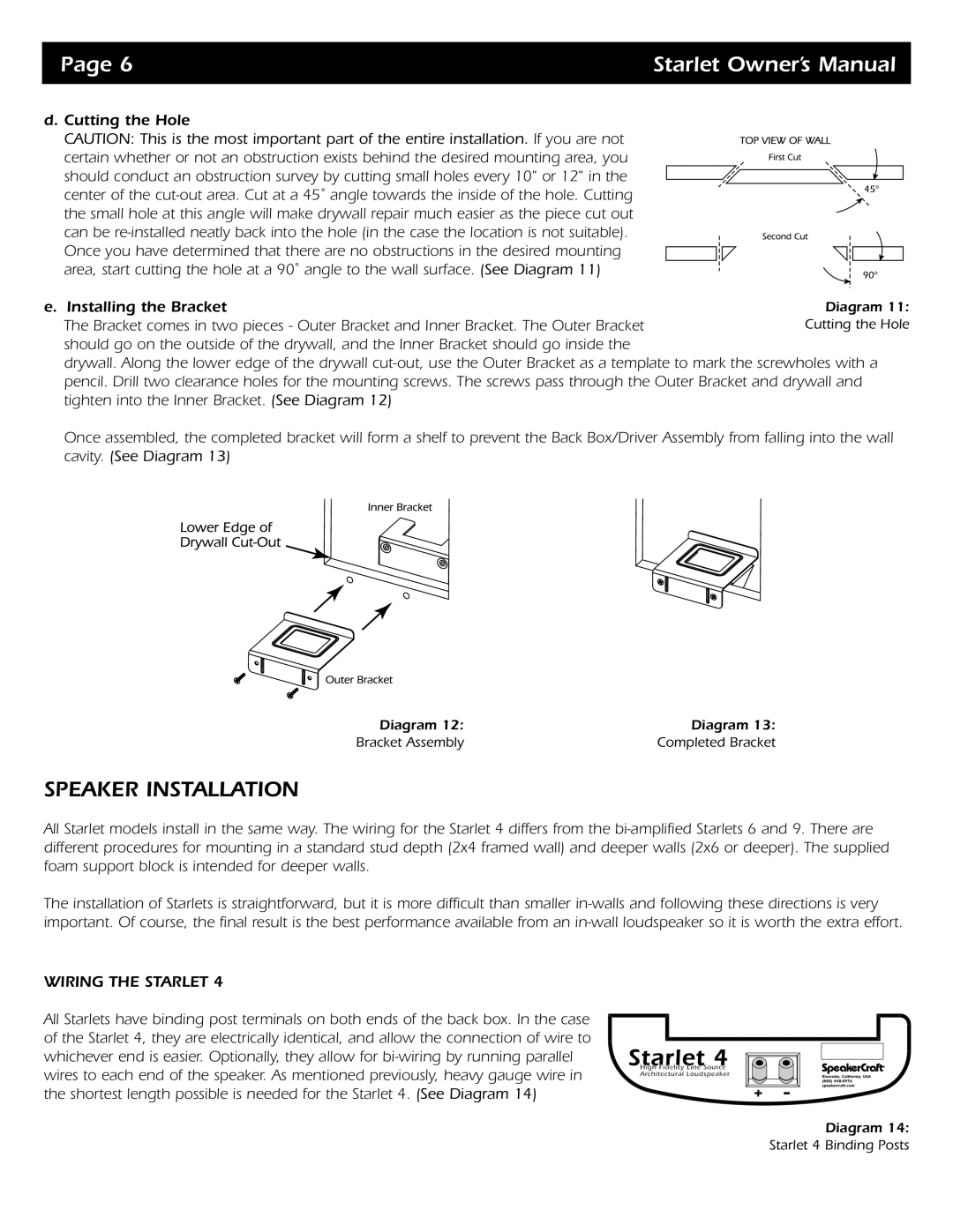
Starlet 4, Starlet 6, Starlet 9 specifications
The SpeakerCraft Starlet series consists of three impressive models: Starlet 4, Starlet 6, and Starlet 9, designed to bring unparalleled audio experiences to both home and professional environments. These speakers exemplify cutting-edge technology, innovative design, and high-quality sound reproduction, catering to diverse listening preferences.The Starlet 4 is an ideal choice for audiophiles seeking compact yet powerful performance. Featuring a dual 4-inch driver configuration, it delivers rich midrange and crisp highs, ensuring a well-balanced sound profile. The speaker utilizes advanced materials for its drivers, minimizing distortion and enhancing clarity. The Starlet 4 is designed for versatility, easily integrating into both wired and wireless setups, thanks to its Bluetooth connectivity and a wide range of input options.
Stepping up to the Starlet 6, this model is equipped with more robust features tailored to larger spaces and more demanding audio needs. The Starlet 6 incorporates a dual 6-inch driver system, which significantly enhances bass response while maintaining the clarity and detail that SpeakerCraft is known for. With an updated DSP (Digital Signal Processing) engine, the Starlet 6 enables users to customize sound profiles according to room acoustics. Its sleek, modern design allows for seamless installation in various settings, making it a perfect addition to any home theater or music studio.
Finally, the Starlet 9 is the flagship model within the series, designed for those who refuse to compromise on audio fidelity. Integrating a tri-axial configuration, the Starlet 9 includes two 9-inch woofers, a powerful midrange driver, and an advanced silk dome tweeter for exceptional sound definition across the frequency spectrum. The speaker features high-efficiency amplification technology, allowing it to deliver superb sound output even at lower volumes. Its sophisticated networked capabilities enable users to connect multiple speakers for a truly immersive multi-room audio experience.
All models in the Starlet series are built with durability and longevity in mind, using high-quality materials that ensure reliable performance. Their elegant aesthetic, combined with significant technological advancements, makes the SpeakerCraft Starlet series a formidable choice for those seeking outstanding sound quality in any setting. Whether for casual listening or professional applications, these speakers provide the versatility and performance required to elevate audio enjoyment to new heights.