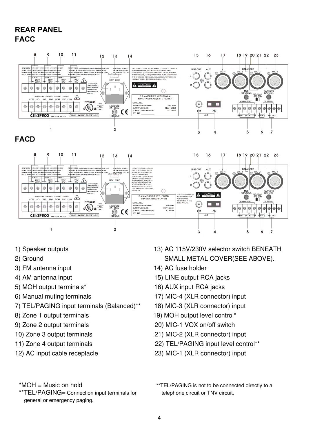
REAR PANEL
FACC |
|
|
|
|
|
|
|
|
|
|
|
|
|
8 | 9 | 10 | 11 | 12 | 13 | 14 | 15 | 16 | 17 | 18 19 | 20 21 | 22 | 23 |
|
| 1 |
|
| 2 |
| 3 |
| 4 | 5 | 6 |
| 7 |
|
|
|
|
|
|
|
|
| |||||
FACD |
|
|
|
|
|
|
|
|
|
|
|
|
|
8 | 9 | 10 | 11 | 12 | 13 | 14 | 15 | 16 | 17 | 18 19 | 20 21 | 22 | 23 |
1 | 2 | 3 | 4 | 5 | 6 | 7 |
|
|
1) | Speaker outputs | 13) | AC 115V/230V selector switch BENEATH |
2) Ground |
| SMALL METAL COVER(SEE ABOVE). | |
3) | FM antenna input | 14) | AC fuse holder |
4) | AM antenna input | 15) LINE output RCA jacks | |
5) | MOH output terminals* | 16) AUX input RCA jacks | |
6) | Manual muting terminals | 17) | |
7) | TEL/PAGING input terminals (Balanced)** | 18) | |
8) | Zone 1 output terminals | 19) MOH output level control* | |
9) | Zone 2 output terminals | 20) | |
10) | Zone 3 output terminals | 21) |
11) | Zone 4 output terminals | 22) TEL/PAGING input level control** |
12) | AC input cable receptacle | 23) |
*MOH = Music on hold | **TEL/PAGING is not to be connected directly to a |
**TEL/PAGING= Connection input terminals for | telephone circuit or TNV circuit. |
general or emergency paging. |
|
| 4 |
