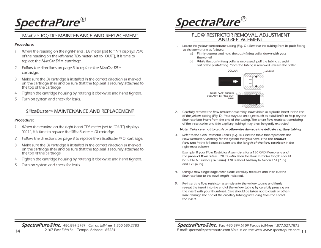
CF-0.5-10, SF-MT-0.5-10, MEM-90,150 specifications
Spectra Watermakers is renowned for its advanced water desalination technology, providing reliable fresh water solutions for various applications. Among their notable products are the CF-0.5-10, SF-MT-0.5-10, MEM-90, and MEM-150 systems, each designed to meet specific water production needs while maintaining ease of use and efficiency.The CF-0.5-10 model is a compact and highly efficient watermaker that delivers up to 10 gallons per hour. Its primary feature is reverse osmosis technology, which effectively removes salt and impurities from seawater, resulting in high-quality potable water. The system is equipped with an energy recovery device that minimizes energy consumption, making it a sustainable choice for boaters and coastal residents alike. With a lightweight design, the CF-0.5-10 is easy to install and maintain, ensuring that users can consistently access fresh water in remote locations.
The SF-MT-0.5-10 is another impressive model from Spectra Watermakers. It offers similar efficiency and capacity but includes additional features for marine applications. This model utilizes a high-quality stainless steel frame and marine-grade components, enhancing durability amidst harsh conditions. The SF-MT-0.5-10 includes an intuitive user interface, allowing for easy operation and monitoring of water production levels. Its compact size makes it suitable for installation in tight spaces on yachts or small vessels.
For those needing larger production capacities, the MEM-90 and MEM-150 systems provide impressive output. The MEM-90 can produce up to 90 gallons per day, while the MEM-150 takes it a step further with a daily capacity of 150 gallons. Both systems leverage advanced membrane technology, ensuring robust performance and long-term reliability. Features such as automatic pressure regulation and user-friendly digital controls provide operators with a seamless experience.
Additionally, these systems are designed with energy efficiency in mind, employing innovative technologies to reduce power consumption. Their rugged construction ensures that they can withstand various environmental stresses, making them ideal for use in both commercial and recreational settings.
In conclusion, Spectra Watermakers’ CF-0.5-10, SF-MT-0.5-10, MEM-90, and MEM-150 systems exemplify quality and innovation in water desalination. Each model brings unique features to meet diverse needs, ensuring that users have a reliable source of fresh water wherever they may be. Whether for marine use or land-based applications, Spectra’s watermakers guarantee performance, efficiency, and durability.

