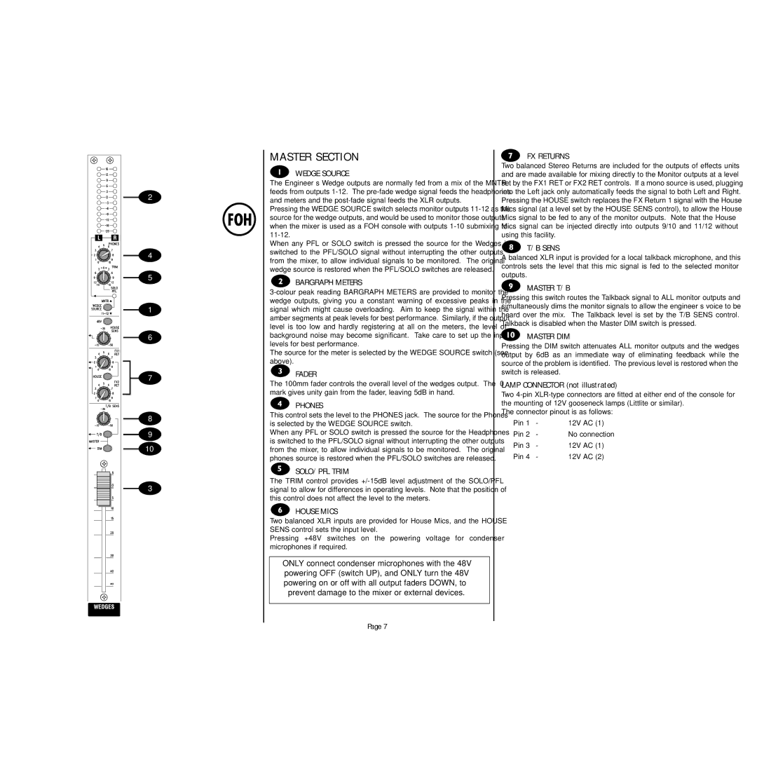
2
4
5
1
6
7
8
9
10
3
MASTER SECTION
WEDGE SOURCE
The Engineer’s Wedge outputs are normally fed from a mix of the MNTR feeds from outputs
Pressing the WEDGE SOURCE switch selects monitor outputs
When any PFL or SOLO switch is pressed the source for the Wedges is switched to the PFL/SOLO signal without interrupting the other outputs from the mixer, to allow individual signals to be monitored. The original wedge source is restored when the PFL/SOLO switches are released.
BARGRAPH METERS
The source for the meter is selected by the WEDGE SOURCE switch (see above).
FADER
The 100mm fader controls the overall level of the wedges output. The ‘0’ mark gives unity gain from the fader, leaving 5dB in hand.
PHONES
This control sets the level to the PHONES jack. The source for the Phones is selected by the WEDGE SOURCE switch.
When any PFL or SOLO switch is pressed the source for the Headphones is switched to the PFL/SOLO signal without interrupting the other outputs from the mixer, to allow individual signals to be monitored. The original phones source is restored when the PFL/SOLO switches are released.
SOLO/PFL TRIM
The TRIM control provides
HOUSE MICS
Two balanced XLR inputs are provided for House Mics, and the HOUSE SENS control sets the input level.
Pressing +48V switches on the powering voltage for condenser microphones if required.
ONLY connect condenser microphones with the 48V powering OFF (switch UP), and ONLY turn the 48V powering on or off with all output faders DOWN, to prevent damage to the mixer or external devices.
Page 7
FX RETURNS
Two balanced Stereo Returns are included for the outputs of effects units and are made available for mixing directly to the Monitor outputs at a level set by the FX1 RET or FX2 RET controls. If a mono source is used, plugging into the Left jack only automatically feeds the signal to both Left and Right. Pressing the HOUSE switch replaces the FX Return 1 signal with the House Mics signal (at a level set by the HOUSE SENS control), to allow the House Mics signal to be fed to any of the monitor outputs. Note that the House Mics signal can be injected directly into outputs 9/10 and 11/12 without using this facility.
T/B SENS
A balanced XLR input is provided for a local talkback microphone, and this controls sets the level that this mic signal is fed to the selected monitor outputs.
MASTER T/B
Pressing this switch routes the Talkback signal to ALL monitor outputs and simultaneously dims the monitor signals to allow the engineer’s voice to be heard over the mix. The Talkback level is set by the T/B SENS control. Talkback is disabled when the Master DIM switch is pressed.
MASTER DIM
Pressing the DIM switch attenuates ALL monitor outputs and the wedges output by 6dB as an immediate way of eliminating feedback while the source of the problem is identified. The previous level is restored when the switch is released.
LAMP CONNECTOR (not illustrated)
Two
The connector pinout is as follows:
Pin 1 | - | 12V AC (1) |
Pin 2 | - | No connection |
Pin 3 | - | 12V AC (1) |
Pin 4 | - | 12V AC (2) |
