Setting Up & Troubleshooting
Initial Set Up
Once you have connected up your system (see the sections on connection and wiring earlier in this manual for guidance) you are ready to set initial positions for the controls on your mixer.
The front panel drawing on page 17 shows typical initial control positions which may serve as a useful guide to setting up the mixer for the first time.
Set up individual input channel as follows:
lConnect your sources (microphone, keyboard etc.) to the required inputs. Note: Phantom powered mics should be connected before the 48V is switched on.
The input provides very wide gain range without the need for a pad. When using LINE level sources, set the INPUT SENS control fully anticlockwise as a preliminary position.
lSet Monitor faders at 0, input faders at 0, and set power amplifier levels to suit the application. Make sure that the EQ switches are released to bypass the EQ sections.
lProvide a typical performance level signal and press the PFL button on the first channel, monitoring the level on the L/R bargraph meters.
lAdjust the input sensitivity until the meter display is in the amber section, with occasional peaks to the first red LED at a typical maximum source level. This allows sufficient headroom to accommodate peaks and establishes the maximum level for normal operation (but see note below).
lFeed the signal to selected monitor outputs by setting the appropriate monitor sends to an initial working level (approx. position 7 on the send knob). Listen to the signal by feeding the selected monitor signal to the engineer’s wedge by turning up the MNTR control on the appropriate outputs, checking that the wedge source is selected to MNTR.
lRepeat this procedure on other channels as required. As more channels are added to the mix, the meters may move into the red section. Adjust the overall level using the Monitor Output faders if necessary.
lListen carefully for the characteristic sound of `feedback’. If you cannot achieve satisfactory input level setting without feedback, check microphone and speaker placement and repeat the exercise. If feedback persists, it may be necessary to use a Graphic Equaliser to reduce the system response at particular resonant frequencies.
Note: The initial settings should only be regarded as a starting point for your mix. It is important to remember that many factors affect the sound during a live performance, for instance the channel EQ settings or even the size of the audience!
Each monitor mix can now be built up progressively, listening carefully for each component in the mix and watching the meters for any hint of overload. If this occurs, back off the appropriate Input Fader slightly until the level is out of the red segments, or adjust the Monitor Faders.
Troubleshooting
No Power
lIs the mains supply present? Check the mains outlet with another device.
lIs the power lead firmly connected?
Condenser Mic Not Working
lIs the 48V turned on?
lIs there an unbalanced device connected to the SPLIT OUT connector?
lIs the mic cable a balanced
Meters not showing any signal
lHas the input gain been set correctly (see above)?
lAre the Monitor faders set at a working level., and are input faders set high enough?
lIs the MUTE switch released on the relevant channels?
lIf monitoring on the wedge outputs, is the appropriate Monitor output feeding the wedges (MNTR control set to working level), and the wedge source selected to MNTR?
lIs there a PFL/AFL pressed on another channel?
No Monitor output, or output low level
lIs the MUTE switch released?
lIs a Graphic EQ or other external device connected to the graphic Insert, and is this device switched on and set up correctly?
lAre the local or Master DIM or T/B switches released?
Headphones Distorting
lAre the headphones less than 200W impedance?
lIs the Phones level set too high?
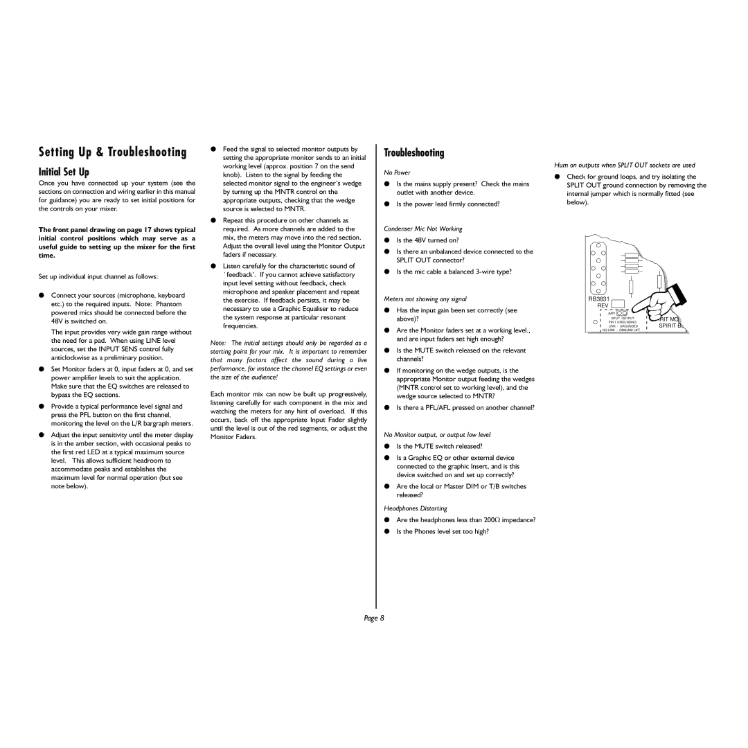
Hum on outputs when SPLIT OUT sockets are used
lCheck for ground loops, and try isolating the SPLIT OUT ground connection by removing the internal jumper which is normally fitted (see below).
RB3831 |
| |
REV |
| |
JMP1 |
| |
SPLIT OUTPUT | SPIRIT MO | |
PIN 1 GROUNDING | ||
SPIRIT B | ||
LINK - GROUNDED | ||
NO LINK - GROUND LIFT |
|
Page 8