ASSEMBLY INSTRUCTIONS
STEP 2
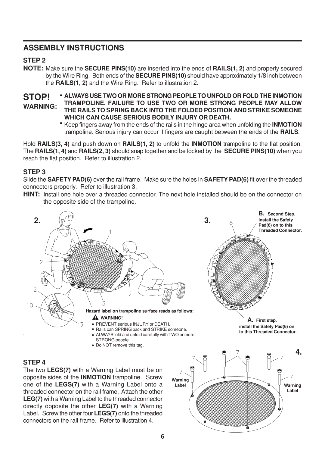
NOTE: Make sure the SECURE PINS(10) are inserted into the ends of RAILS(1, 2) and properly secured by the Wire Ring. Both ends of the SECURE PINS(10) should have approximately 1/8 inch between the RAILS(1, 2) and the Wire Ring. Refer to illustration 2.
STOP! | ALWAYS USE TWO OR MORE STRONG PEOPLE TO UNFOLD OR FOLD THE INMOTION |
WARNING: | TRAMPOLINE. FAILURE TO USE TWO OR MORE STRONG PEOPLE MAY ALLOW |
| THE RAILS TO SPRING BACK INTO THE FOLDED POSITION AND STRIKE SOMEONE |
| WHICH CAN CAUSE SERIOUS BODILY INJURY OR DEATH. |
| Keep fingers away from the ends of the rails in the hinge area when unfolding the INMOTION |
| trampoline. Serious injury can occur if fingers are caught between the ends of the RAILS. |
Hold RAILS(3, 4) and push down on RAILS(1, 2) to unfold the INMOTION trampoline to the flat position. The RAILS(1, 4) and RAILS(2, 3) should snap together and be locked by the SECURE PINS(10) when you reach the flat position. Refer to illustration 2.
STEP 3
Slide the SAFETY PAD(6) over the rail frame. Make sure the holes in SAFETY PAD(6) fit over the threaded connectors properly. Refer to illustration 3.
HINT: Install one hole over a threaded connector. The next hole installed should be on the connector on the opposite side of the trampoline.
2. | 3. | B. Second Step, |
install the Safety | ||
|
| Pad(6) on to this |
Threaded Connector.
Hazard label on trampoline surface reads as follows:
!WARNING!
![]() PREVENT serious INJURY or DEATH.
PREVENT serious INJURY or DEATH.
![]() Rails can SPRING back and STRIKE someone.
Rails can SPRING back and STRIKE someone.
![]() ALWAYS fold and unfold carefully with TWO or more
ALWAYS fold and unfold carefully with TWO or more
STRONG people.
![]() Do NOT remove this tag.
Do NOT remove this tag.
STEP 4
The two LEGS(7) with a Warning Label must be on
opposite sides of the INMOTION trampoline. Screw | Warning |
one of the LEGS(7) with a Warning Label onto a | Label |
threaded connector on the rail frame. Attach the other |
|
LEG(7) with a Warning Label to the threaded connector |
|
directly opposite the other LEG(7) with a Warning |
|
Label. Screw the other four LEGS(7) onto the threaded |
|
connectors on the rail frame. Refer to illustration 4. |
|
A.First step,
install the Safety Pad(6) on to this Threaded Connector.
4.
Warning
Label
6