ASSEMBLY INSTRUCTIONS
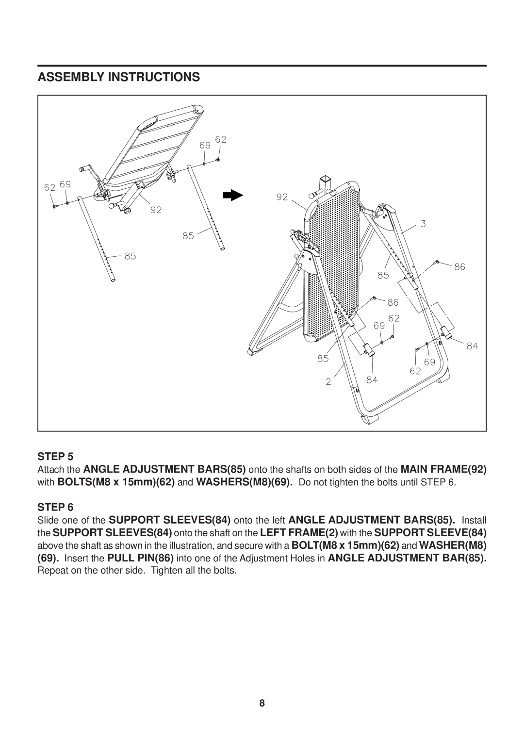
STEP 5
Attach the ANGLE ADJUSTMENT BARS(85) onto the shafts on both sides of the MAIN FRAME(92) with BOLTS(M8 x 15mm)(62) and WASHERS(M8)(69). Do not tighten the bolts until STEP 6.
STEP 6
Slide one of the SUPPORT SLEEVES(84) onto the left ANGLE ADJUSTMENT BARS(85). Install the SUPPORT SLEEVES(84) onto the shaft on the LEFT FRAME(2) with the SUPPORT SLEEVE(84) above the shaft as shown in the illustration, and secure with a BOLT(M8 x 15mm)(62) and WASHER(M8) (69). Insert the PULL PIN(86) into one of the Adjustment Holes in ANGLE ADJUSTMENT BAR(85). Repeat on the other side. Tighten all the bolts.
8
