DESCRIPTION OF FUNCTIONS
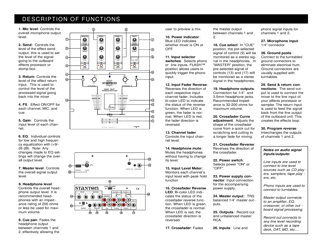
1.Mic level: Controls the overall microphone output level.
2.Send: Controls the level of the effect send output. this is used to set the level of the signal going to the outboard effects processor or stomp box.
3.Return: Controls the level of the effect return input. This is used to control the level of the processed signal going back into the mixer
4.FX: Effect ON/OFF for each channel, MIC, and cue.
5.Gain: Controls the input level of each chan- nel.
6.EQ: Individual controls for low and high frequen- cy equalization with (+9/-
26dB) Note: Any changes made to EQ set- tings will change the over- all output level.
7.Master level: Controls the overall signal output level.
8.Headphone level: Controls the overall head- phone output level. It is recommended head- phones with an imped- ance rating of 200 ohms or less be used for maxi- mum volume.
9.Cue pan: Fades the headphone output between channels 1 and 2, effectively allowing the
user to preview a mix.
10.Power indicator: Blue LED indicates whether mixer is ON or OFF.
11.Input selector switches: Selects phono or line inputs. FLASH™ position allows users to quickly trigger the phono input.
12.Input Fader Reverse: Reverses the direction of each respective input channel fader. Includes
13.Channel fader: Controls the input chan- nel level.
14.Headphone mute: Mutes the headphones without having to change its level.
15.Input Level Meter: Monitors each channel’s input level with peak hold function
16.Crossfader Reverse LED:
17.Crossfader: Fades
the master output between channels 1 and 2.
18.Cue select: In "CUE" position, the
19.Headphone outputs: Connection for 1/4” and 3.5mm headphone jacks. Recommended imped- ance is
20.Crossfader Curve adjustment: Adjusts the shape of the crossfader curve from a quick cut for scratching and cutting to a longer fade for mixing.
21.Crossfader Reverse: Reverses the direction of the crossfader.
22.Power switch: Selects power "ON" or "OFF".
23.Power supply con- nector: Input connection for the accompanying power supply.
24.Master output: TRS balanced 1/4” master out - puts.
25.Outputs: Record out and unbalanced master RCA.
26.Inputs: Line and
phono signal inputs for channels 1 and 2.
27.Microphone input: 1/4” connector
28.Ground posts : Connect to the turntables’ ground connectors to eliminate electrical hum. Ground connectors are usually supplied with turntables.
29.Send & return con- nections: The send out- put is used to connect the mixer to the line input of your effects processor or sampler. The return input is used to feed the signal back from the line output of the outboard unit. This creates the effects loop.
30.Program reverse: Interchanges the outputs of channels 1 and 2.
Notes on audio signal inputs/outputs:
Line inputs are used to connect to line level sources such as CD play - ers, samplers, tape play - ers, etc.
Phono inputs are used to connect to turntables.
Master output connects to an amplifier, EQ, crossover, or other out - board signal processing.
Record out connects to any line level recording device such as a tape deck, DAT, MD, etc....