Stanton ST-150 owner manual Assembly, Tone Arm And Cartridge Settings, Connections

Models: ST-150

1 6
Download 6 pages 3.11 Kb
Page 4
Image 4
ASSEMBLY

ASSEMBLY


TONE ARM AND CARTRIDGE SETTINGS

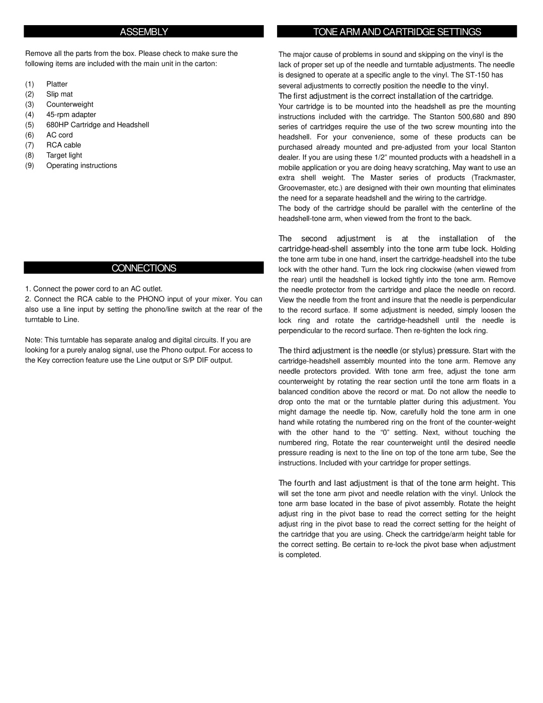
Remove all the parts from the box. Please check to make sure the following items are included with the main unit in the carton:

(1)Platter

(2)Slip mat

(3)Counterweight

(4)45-rpm adapter

(5)680HP Cartridge and Headshell

(6)AC cord

(7)RCA cable

(8)Target light

(9)Operating instructions

CONNECTIONS

1.Connect the power cord to an AC outlet.

2.Connect the RCA cable to the PHONO input of your mixer. You can also use a line input by setting the phono/line switch at the rear of the turntable to Line.

Note: This turntable has separate analog and digital circuits. If you are looking for a purely analog signal, use the Phono output. For access to the Key correction feature use the Line output or S/P DIF output.

The major cause of problems in sound and skipping on the vinyl is the lack of proper set up of the needle and turntable adjustments. The needle is designed to operate at a specific angle to the vinyl. The ST-150 has several adjustments to correctly position the needle to the vinyl.

The first adjustment is the correct installation of the cartridge.

Your cartridge is to be mounted into the headshell as pre the mounting instructions included with the cartridge. The Stanton 500,680 and 890 series of cartridges require the use of the two screw mounting into the headshell. For your convenience, some of these products can be purchased already mounted and pre-adjusted from your local Stanton dealer. If you are using these 1/2” mounted products with a headshell in a mobile application or you are doing heavy scratching, May want to use an extra shell weight. The Master series of products (Trackmaster, Groovemaster, etc.) are designed with their own mounting that eliminates the need for a separate headshell and the wiring to the cartridge.

The body of the cartridge should be parallel with the centerline of the headshell-tone arm, when viewed from the front to the back.

The second adjustment is at the installation of the cartridge-head-shell assembly into the tone arm tube lock. Holding the tone arm tube in one hand, insert the cartridge-headshell into the tube lock with the other hand. Turn the lock ring clockwise (when viewed from the rear) until the headshell is locked tightly into the tone arm. Remove the needle protector from the cartridge and place the needle on record. View the needle from the front and insure that the needle is perpendicular to the record surface. If some adjustment is needed, simply loosen the lock ring and rotate the cartridge-headshell until the needle is perpendicular to the record surface. Then re-tighten the lock ring.

The third adjustment is the needle (or stylus) pressure. Start with the cartridge-headshell assembly mounted into the tone arm. Remove any needle protectors provided. With tone arm free, adjust the tone arm counterweight by rotating the rear section until the tone arm floats in a balanced condition above the record or mat. Do not allow the needle to drop onto the mat or the turntable platter during this adjustment. You might damage the needle tip. Now, carefully hold the tone arm in one hand while rotating the numbered ring on the front of the counter-weight with the other hand to the “0” setting. Next, without touching the numbered ring, Rotate the rear counterweight until the desired needle pressure reading is next to the line on top of the tone arm tube, See the instructions. Included with your cartridge for proper settings.

The fourth and last adjustment is that of the tone arm height. This will set the tone arm pivot and needle relation with the vinyl. Unlock the tone arm base located in the base of pivot assembly. Rotate the height adjust ring in the pivot base to read the correct setting for the height adjust ring in the pivot base to read the correct setting for the height of the cartridge that you are using. Check the cartridge/arm height table for the correct setting. Be certain to re-lock the pivot base when adjustment is completed.
Page 4
Image 4
Stanton ST-150 owner manual Assembly, Tone Arm And Cartridge Settings, Connections