Manuals
/
Star Micronics
/
Computer Equipment
/
Printer
Star Micronics
TUP500
technical manual
Printer Mechanism Unit, Disassembly Drawing
Models:
TUP500
1
22
70
70
Download
70 pages
49.22 Kb
19
20
21
22
23
24
25
26
Parts list
Block Diagram
Maintenance
Printer Assembly
Chapter Adjustments
How to
Page 22
Image 22
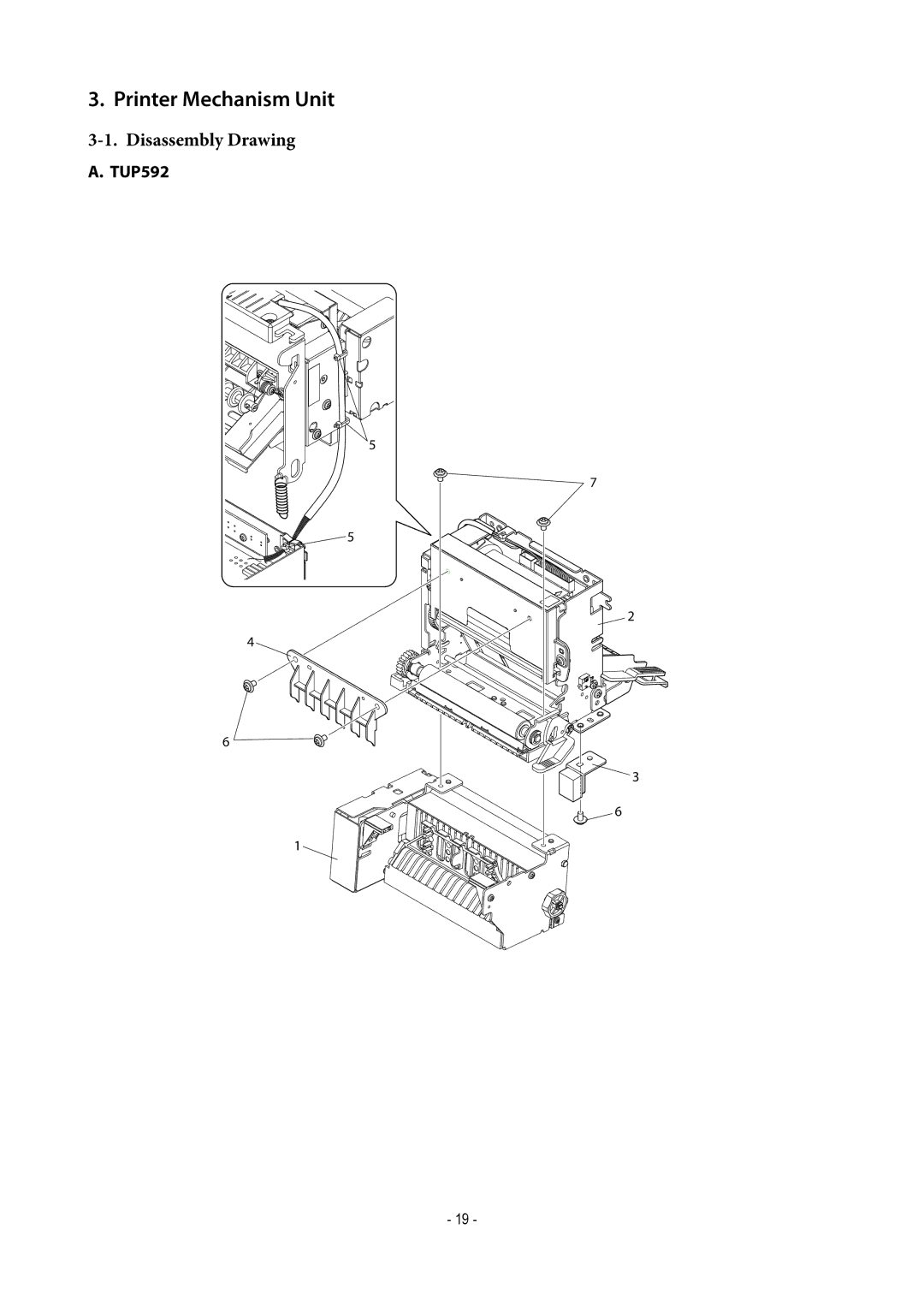
3. Printer Mechanism Unit
3-1.
Disassembly Drawing
A. TUP592
5
5
4
6
1
7
2
3
6
- 19 -
Page 21
Page 23
Page 22
Image 22
Page 21
Page 23
Contents
TUP500 Series
Page
Introduction
Chapter Adjustments
Sensor Adjustment
Adjustment of the PE/BM Sensor
This completes the PE/BM sensor adjustment
Adjustment of the NE Sensor TUP592 Only
Adjustment of the Presenter Sensor
This completes the Presenter sensor adjustment
Chapter Maintenance and Lubrication
Maintenance
Periodic Maintenance
How to Release the Cutter Lock
Handling Paper Jams
Lubricating Method
Lubrication
Lubricant
Lubricated Areas
Lubricated Areas TMP542
Chapter Parts List
Printer Assembly
Disassembly Drawing
TUP542
Parts List
Mechanism Base Unit
TUP542
Handle TUP9
Printer Mechanism Unit
1814
Stopper Unit TMP5
Spring Holder Unit TMP9
Sub-Assembly
Frame R Unit
Frame L Unit
Board chassis L Unit
Presenter Unit PR521
Terminal Board Unit PR5
Paper Guide Unit PR521
Guide Frame Unit
Head Unit
Platen Holder Unit
Paper Guide Unit
Block Diagram
CPU Eeprom
CircuitDiagram
Main Logic Board 2/5
Main Logic Board 3/5
Logic
Board
Main Logic Board 5/5
Component Layout
Circuit Number Diagram
CERA.CAPA.CHIP1608 0.1UF
Schottky Diode Chip SX34 DSW1
DRWG.NO REV Parts no
Chip Resistor 0 OHM 1/10W
Chip Transistor KTC3875S-G*AL
Sub Board
Circuit Diagram
Component Layou Parts List
Sub Board
Control Panel Board
Component Layout Parts List
Control Panel Board
Snout Board
Snout Board
Serial Interface Board 25pin
Serial Interface Board 25pin
Serial Interface Board 9pin
Serial Interface Board 9pin
Parallel Interface Board
Parallel Interface Board
Part marked with two asterisks ** is not mounted
Component Layout
USB Interface Board
BAR Code Label LBP-80141
Board
Ethernet Interface Board 2/5
Ethernet Interface Board 3/5
Ethernet
Interface Board
Interface
Component Layout
Ethernet Interface Board
Chip Resistore 100 K-OHM 1/16W
Not Mounted Not Used
Overseas Subsidiary Companies Star Micronics AMERICA, INC
Top
Page
Image
Contents