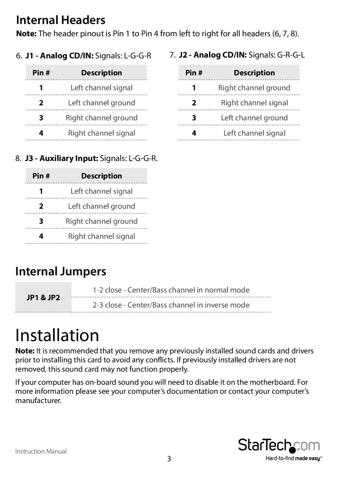
Internal Headers
Note: The header pinout is Pin 1 to Pin 4 from left to right for all headers (6, 7, 8).
6. J1 - Analog CD/IN: Signals: | 7. J2 - Analog CD/IN: Signals: | ||
Pin # | Description | Pin # | Description |
1 | Left channel signal | 1 | Right channel ground |
2 | Left channel ground | 2 | Right channel signal |
3 | Right channel ground | 3 | Left channel ground |
4 | Right channel signal | 4 | Left channel signal |
8.J3 - Auxiliary Input: Signals: L-G-G-R.
Pin # | Description |
1Left channel signal
2Left channel ground
3Right channel ground
4Right channel signal
Internal Jumpers
JP1 & JP2
Installation
Note: It is recommended that you remove any previously installed sound cards and drivers prior to installing this card to avoid any conflicts. If previously installed drivers are not removed, this sound card may not function properly.
If your computer has
Instruction Manual
3