TYPICAL INSTALLATION
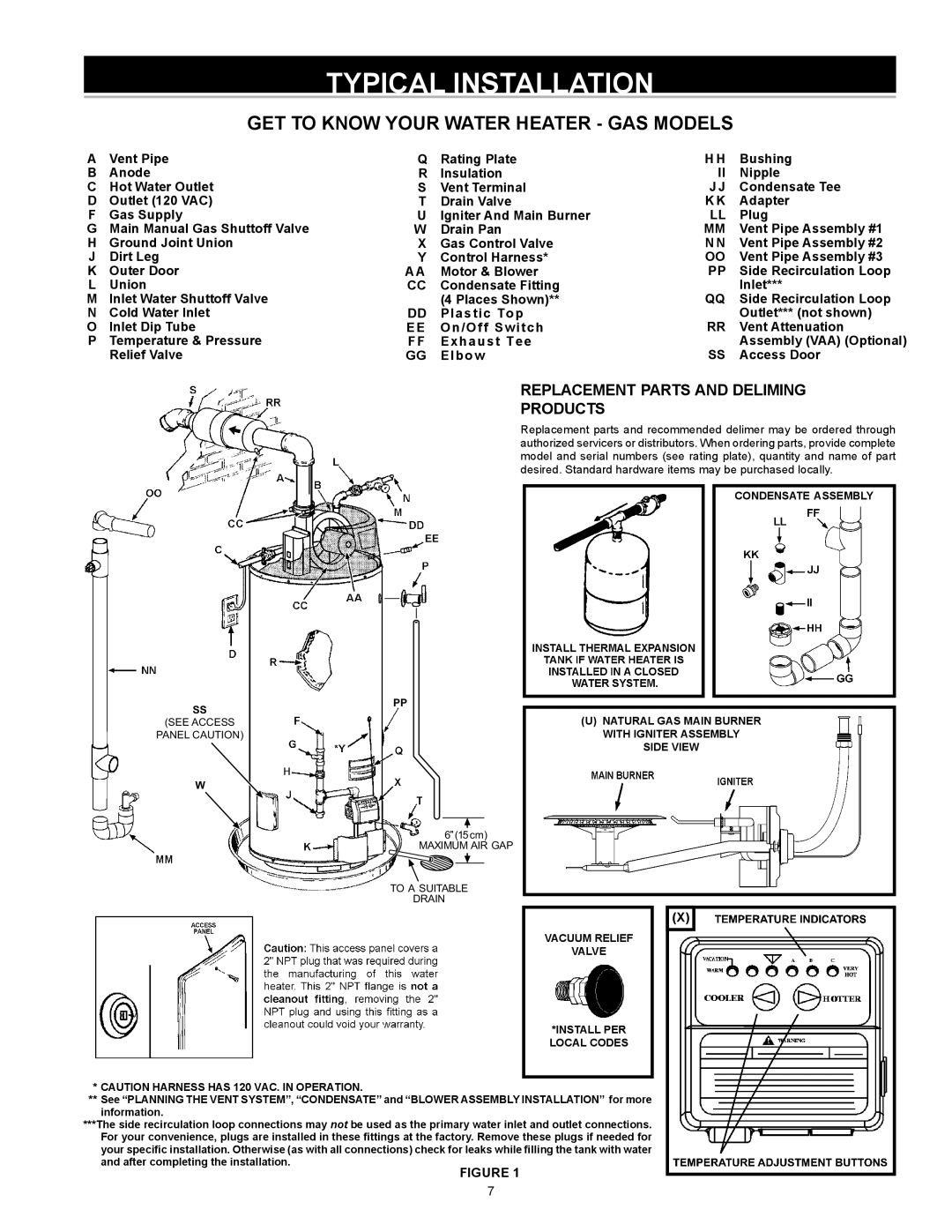
GET TO KNOW YOUR WATER HEATER - GAS MODELS
AVent Pipe
BAnode
CHot Water Outlet
D Outlet (120 VAC)
FGas Supply
GMain Manual Gas Shuttoff Valve
HGround Joint Union J Dirt Leg
KOuter Door
LUnion
MInlet Water Shuttoff Valve
NCold Water Inlet
OInlet Dip Tube
PTemperature & Pressure Relief Valve
Q | Rating Plate | H H | Bushing |
R | Insulation | II | Nipple |
S | Vent Terminal | JJ | Condensate Tee |
T | Drain Valve | KK | Adapter |
U | Igniter And Main Burner | LL | Plug |
W | Drain Pan | MM | Vent Pipe Assembly #1 |
X | Gas Control Valve | NN | Vent Pipe Assembly #2 |
Y | Control Harness* | OO | Vent Pipe Assembly #3 |
AA | Motor & Blower | PP | Side Recirculation Loop |
CC | Condensate Fitting | Inlet*** | |
DD | (4 Places Shown)** | Side Recirculation Loop | |
Plastic Top | RR | Outlet*** (not shown) | |
EE | On/Off Switch | Vent Attenuation | |
FF | Exhaust Tee | SS | Assembly (VAA) (Optional) |
GG | Elbow | Access Door |
REPLACEMENT PARTS AND DELIMING
PRODUCTS
Replacement parts and recommended delimer may be ordered through authorized servicers or distributors. When ordering parts, provide complete model and serial numbers (see rating plate), quantity and name of part desired. Standard hardware items may be purchased locally.
SS
(SEE ACCESS
PANEL CAUTION)
W
PP
6 (15cm)
MAXIMUM AIR GAP
TO A SUITABLE
DRAIN
CONDENSATE ASSEMBLY
(U)NATURAL GAS MAIN BURNER
WITH IGNITER ASSEMBLY
SIDE VIEW
(X)
