personnel or damage to equipment before any disassembly of the brake is attempted or before the manual release lever is operated on the brake.
2.Observe all cautions listed at the beginning of this manual before attempting to service brake.
3.Remove housing screws (15) and housing (7) or (7A).
Wear adjustment
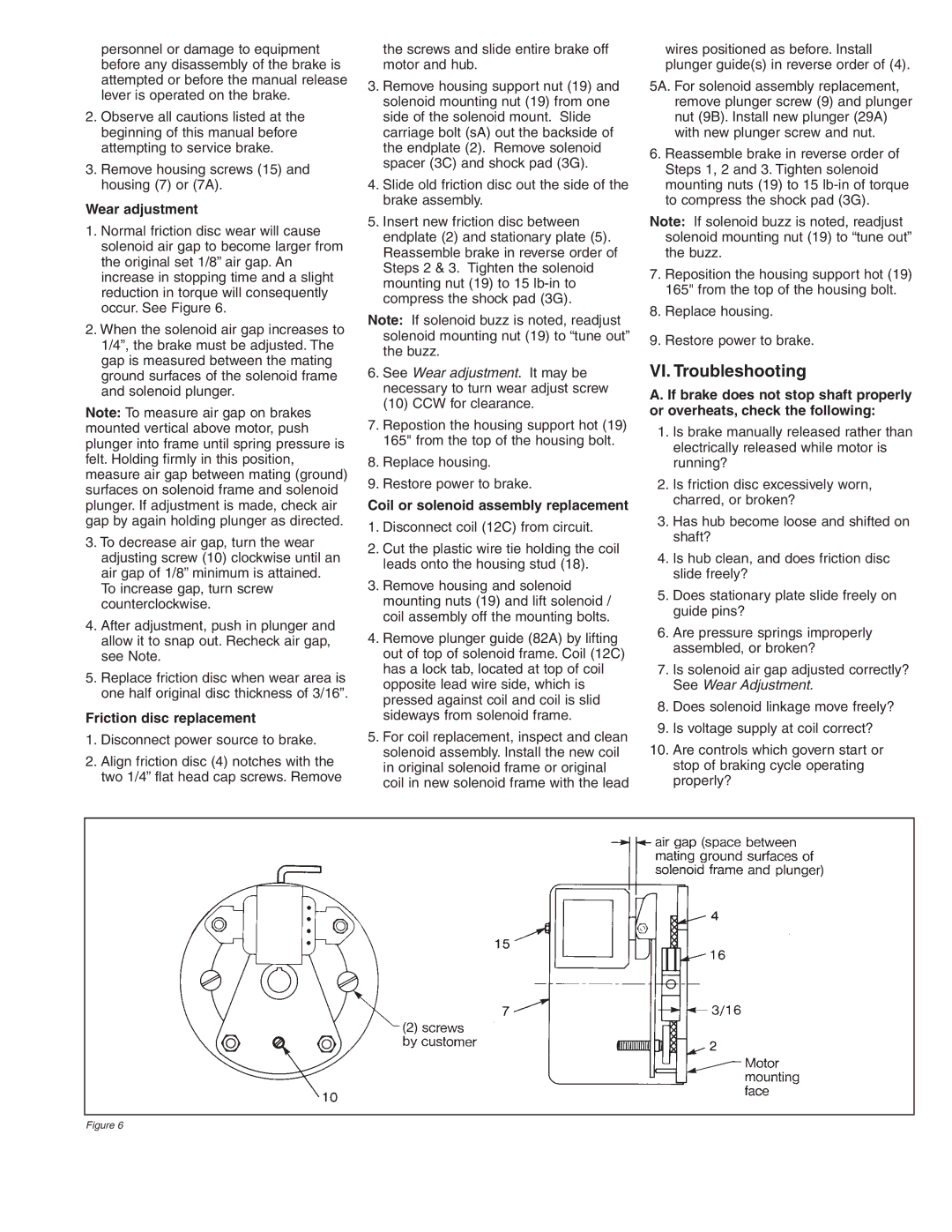
1.Normal friction disc wear will cause solenoid air gap to become larger from the original set 1/8” air gap. An increase in stopping time and a slight reduction in torque will consequently occur. See Figure 6.
2.When the solenoid air gap increases to 1/4”, the brake must be adjusted. The gap is measured between the mating ground surfaces of the solenoid frame and solenoid plunger.
Note: To measure air gap on brakes mounted vertical above motor, push plunger into frame until spring pressure is felt. Holding firmly in this position, measure air gap between mating (ground) surfaces on solenoid frame and solenoid plunger. If adjustment is made, check air gap by again holding plunger as directed.
3.To decrease air gap, turn the wear adjusting screw (10) clockwise until an air gap of 1/8” minimum is attained. To increase gap, turn screw counterclockwise.
4.After adjustment, push in plunger and allow it to snap out. Recheck air gap, see Note.
5.Replace friction disc when wear area is one half original disc thickness of 3/16”.
Friction disc replacement
1.Disconnect power source to brake.
2.Align friction disc (4) notches with the two 1/4” flat head cap screws. Remove
the screws and slide entire brake off motor and hub.
3.Remove housing support nut (19) and solenoid mounting nut (19) from one side of the solenoid mount. Slide carriage bolt (sA) out the backside of the endplate (2). Remove solenoid spacer (3C) and shock pad (3G).
4.Slide old friction disc out the side of the brake assembly.
5.Insert new friction disc between endplate (2) and stationary plate (5). Reassemble brake in reverse order of Steps 2 & 3. Tighten the solenoid mounting nut (19) to 15
Note: If solenoid buzz is noted, readjust solenoid mounting nut (19) to “tune out” the buzz.
6.See Wear adjustment. It may be necessary to turn wear adjust screw (10) CCW for clearance.
7.Repostion the housing support hot (19) 165" from the top of the housing bolt.
8.Replace housing.
9.Restore power to brake.
Coil or solenoid assembly replacement
1.Disconnect coil (12C) from circuit.
2.Cut the plastic wire tie holding the coil leads onto the housing stud (18).
3.Remove housing and solenoid mounting nuts (19) and lift solenoid / coil assembly off the mounting bolts.
4.Remove plunger guide (82A) by lifting out of top of solenoid frame. Coil (12C) has a lock tab, located at top of coil opposite lead wire side, which is pressed against coil and coil is slid sideways from solenoid frame.
5.For coil replacement, inspect and clean solenoid assembly. Install the new coil in original solenoid frame or original coil in new solenoid frame with the lead
wires positioned as before. Install plunger guide(s) in reverse order of (4).
5A. For solenoid assembly replacement, remove plunger screw (9) and plunger nut (9B). Install new plunger (29A) with new plunger screw and nut.
6.Reassemble brake in reverse order of Steps 1, 2 and 3. Tighten solenoid mounting nuts (19) to 15
Note: If solenoid buzz is noted, readjust solenoid mounting nut (19) to “tune out” the buzz.
7.Reposition the housing support hot (19) 165" from the top of the housing bolt.
8.Replace housing.
9.Restore power to brake.
VI. Troubleshooting
A. If brake does not stop shaft properly or overheats, check the following:
1.Is brake manually released rather than electrically released while motor is running?
2.Is friction disc excessively worn, charred, or broken?
3.Has hub become loose and shifted on shaft?
4.Is hub clean, and does friction disc slide freely?
5.Does stationary plate slide freely on guide pins?
6.Are pressure springs improperly assembled, or broken?
7.Is solenoid air gap adjusted correctly? See Wear Adjustment.
8.Does solenoid linkage move freely?
9.Is voltage supply at coil correct?
10.Are controls which govern start or stop of braking cycle operating properly?
Figure 6
