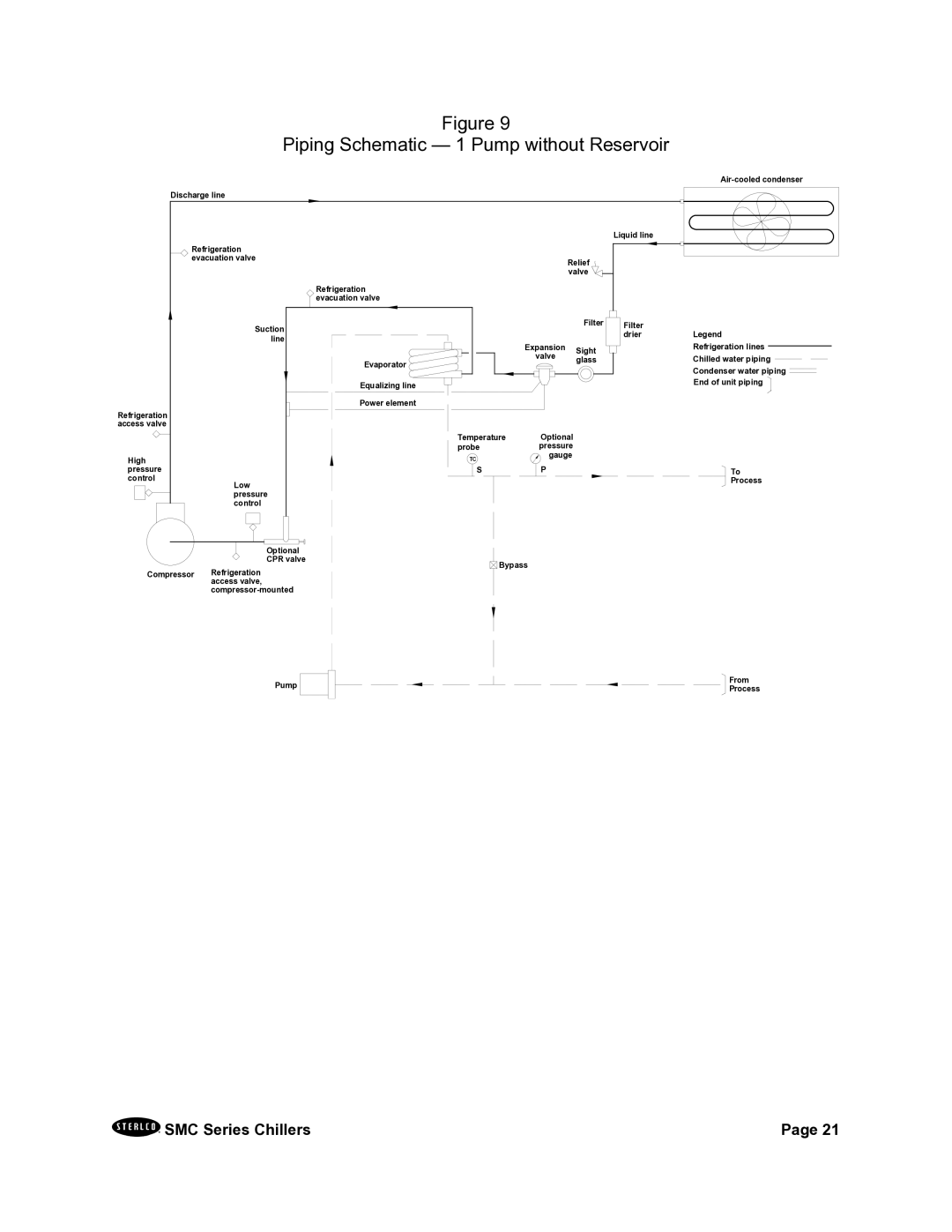
Figure 9
Piping Schematic — 1 Pump without Reservoir
Discharge line
|
|
|
|
| Liquid line |
| Refrigeration |
|
|
|
|
| evacuation valve |
| Relief |
| |
|
|
| valve |
| |
|
| Refrigeration |
|
|
|
|
| evacuation valve |
|
|
|
| Suction |
|
| Filter | Filter |
|
|
|
| drier | |
| line |
|
|
| |
|
| Expansion |
|
| |
|
|
| Sight |
| |
|
|
| valve |
| |
|
| Evaporator | glass |
| |
|
|
|
| ||
|
|
|
|
| |
|
| Equalizing line |
|
|
|
|
| Power element |
|
|
|
Refrigeration |
|
|
|
|
|
access valve |
|
|
|
|
|
|
| Temperature | Optional |
|
|
|
| probe | pressure |
|
|
High |
| TC | gauge |
|
|
pressure |
| S | P |
|
|
control | Low |
|
|
|
|
|
|
|
|
| |
| pressure |
|
|
|
|
| control |
|
|
|
|
| Optional |
|
|
|
|
| CPR valve | Bypass |
|
| |
|
|
|
| ||
Compressor Refrigeration access valve,
Legend Refrigeration lines Chilled water piping Condenser water piping End of unit piping ![]()
To
Process
Pump | From | |
Process | ||
|
SMC Series Chillers | Page 21 |
