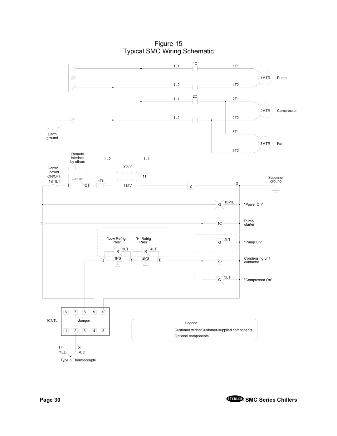
Figure 15
Typical SMC Wiring Schematic
1L1
1C1T1
Earth
ground
Remote |
|
interlock | 1L2 |
by others |
|
Control |
|
power |
|
1L2
1L1
1L2
1L1
230V
2C
1MTR Pump
1T2
2T1
2MTR Compressor
2T2
3T1
3MTR Fan
3T2
ON/OFF | Jumper | 1FU | |
| |||
1 |
| X1 |
1T
115V
|
| Subpanel |
| 2 | ground |
2 |
| |
|
| |
G |
| "Power On" |
31
| "Low Refrig |
| "Hi Refrig | |
| Pres" |
| Pres" |
|
| R 3LT |
| R | 4LT |
41 | 1PS | 51 | 2PS | 61 |
|
| |||
|
|
|
|
|
|
|
|
|
|
|
|
|
| 61 |
| 71 |
| 81 |
| 91 |
| 10 |
|
1CNTL |
|
|
|
| Jumper |
|
|
|
| ||
|
|
|
|
|
|
|
|
|
|
|
|
| 1 | 21 | 31 | 41 | 51 | ||||||
|
|
|
|
|
|
|
|
|
|
|
|
(+)
YEL RED
Type K Thermocouple
1C |
| Pump |
| starter | |
G | 2LT | "Pump On" |
2C |
| Condensing unit |
| contactor | |
G | 5LT | "Compressor On" |
Legend
Customer
Page 30 |
| SMC Series Chillers |
| ||
|