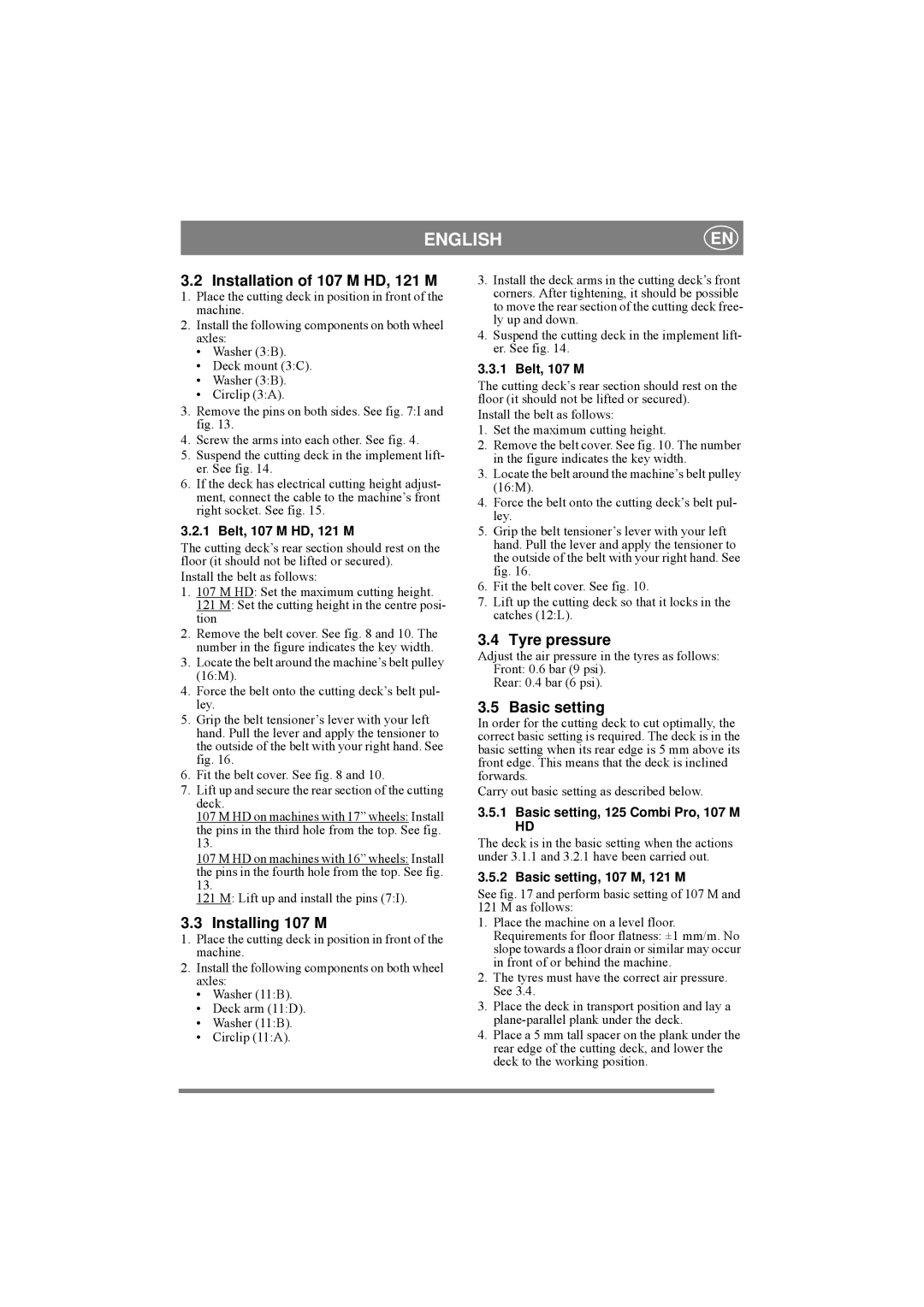
8211-0543-01 specifications
The Stiga 8211-0543-01 is a remarkable piece of equipment designed for those who seek efficiency and performance in their outdoor maintenance tasks. This particular model stands out due to its robust construction and advanced features, making it ideal for both professionals and avid gardeners.One of the key features of the Stiga 8211-0543-01 is its powerful engine, which delivers exceptional performance while maintaining fuel efficiency. The engine is designed to minimize emissions, aligning with the growing demand for environmentally friendly gardening solutions. With a high displacement, the engine ensures that users can complete their tasks quickly and effectively, whether it be lawn maintenance or hedge trimming.
A standout technology incorporated into the Stiga 8211-0543-01 is its ergonomic design. The handle is adjustable and equipped with comfort grips, reducing strain during extended use. This thoughtful design is aimed at providing maximum user comfort, allowing for longer periods of operation without fatigue. Additionally, the balanced weight distribution helps in maneuvering the tool with ease, making it accessible for users of various skill levels.
The cutting blade of the Stiga 8211-0543-01 is another remarkable feature. Constructed from high-quality steel, the blade offers durability and precision, ensuring a clean cut every time. Its design maximizes cutting efficiency, making it effective for tackling thick branches and dense foliage. This is particularly beneficial for maintaining a well-groomed landscape.
Furthermore, the Stiga 8211-0543-01 includes advanced safety features. It comes equipped with a quick-stop system that halts the blade within seconds in case of emergency, reducing the risk of accidents. Additionally, the protective guard shields users from debris, ensuring safer operation.
Maintenance of the Stiga 8211-0543-01 has been made straightforward, with easily accessible components and an intuitive design. Regular upkeep is essential for optimum performance, and this model simplifies the process, allowing users to spend more time tending to their gardens rather than maintaining their tools.
In conclusion, the Stiga 8211-0543-01 is a powerful, efficient, and user-friendly outdoor tool that combines advanced technology with thoughtful design. Its features make it a reliable choice for anyone looking to enhance their gardening experience and achieve professional results.

