6 | Introduction |
Receiving Frame Rear Panel
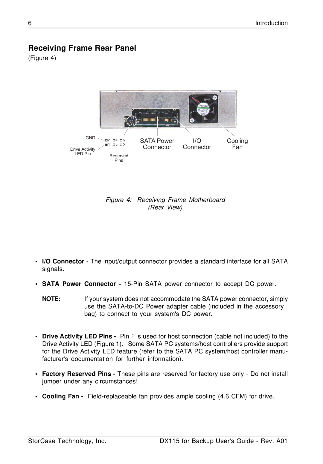
(Figure 4)
GND |
|
|
|
|
|
|
| |
2 | 4 | 6 | SATA Power | I/O | Cooling | |||
| ||||||||
| 1 | 3 | 5 | |||||
| Connector | Connector | Fan | |||||
Drive Activity |
|
|
| |||||
LED Pin | Reserved |
| |
| Pins |
Figure 4: Receiving Frame Motherboard
(Rear View)
•I/O Connector - The input/output connector provides a standard interface for all SATA signals.
•SATA Power Connector -
NOTE: If your system does not accommodate the SATA power connector, simply use the
•Drive Activity LED Pins - Pin 1 is used for host connection (cable not included) to the Drive Activity LED (Figure 1). Some SATA PC systems/host controllers provide support for the Drive Activity LED feature (refer to the SATA PC system/host controller manu- facturer's documentation for further information).
•Factory Reserved Pins - These pins are reserved for factory use only - Do not install jumper under any circumstances!
•Cooling Fan -
StorCase Technology, Inc. | DX115 for Backup User's Guide - Rev. A01 |