INSTALLATION INSTRUCTIONS
SITE REQUIREMENTS
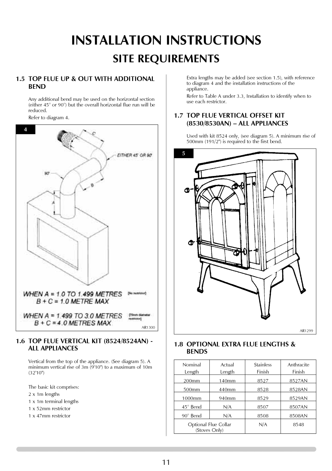
1.5TOP FLUE UP & OUT WITH ADDITIONAL BEND
Any additional bend may be used on the horizontal section (either 45° or 90°) but the overall horizontal flue run will be reduced.
Refer to diagram 4.
4
AR1300
1.6TOP FLUE VERTICAL KIT (8524/8524AN) -
ALL APPLIANCES
Vertical from the top of the appliance. (See diagram 5). A minimum vertical rise of 3m (9'10") to a maximum of 10m (32'10")
The basic kit comprises: 2 x 1m lengths
1 x 1m terminal lengths
1 x 52mm restrictor
1 x 47mm restrictor
Extra lengths may be added (see section 1.5), with reference to diagram 4 and the installation instructions of the appliance.
Refer to Table A under 3.3, Installation to identify when to use each restrictor.
1.7TOP FLUE VERTICAL OFFSET KIT (8530/8530AN) – ALL APPLIANCES
Used with kit 8524 only, (see diagram 5). A minimum rise of 500mm (191/2") is required to the first bend.
5
AR1299
1.8OPTIONAL EXTRA FLUE LENGTHS & BENDS
Nominal | Actual | Stainless | Anthracite |
Length | Length | Finish | Finish |
200mm | 140mm | 8527 | 8527AN |
500mm | 440mm | 8528 | 8528AN |
1000mm | 940mm | 8529 | 8529AN |
45° Bend | N/A | 8507 | 8507AN |
90° Bend | N/A | 8508 | 8508AN |
Optional Flue Collar | N/A | 8548 | |
(Stoves Only) |
|
| |
11
