
Stove Range specifications
Stovax has established itself as a leader in the stove market, renowned for its innovative technologies and commitment to quality. The Stovax Stove Range offers a diverse selection of wood-burning and multi-fuel stoves that combine functionality with aesthetic appeal, ensuring warmth and comfort in any home.One of the standout features of the Stovax Stove Range is its efficient burning technology. Many models are equipped with advanced air wash systems that keep the glass clean, providing an unobstructed view of the flames while maximizing heat output. This technology not only enhances performance but also ensures that your stove operates with reduced emissions, complying with the stringent environmental standards that consumers demand today.
The Stovax range includes a variety of styles and sizes, catering to both contemporary and traditional interiors. From sleek, modern designs to classic, Victorian-inspired stoves, there is a perfect model for every taste and home décor. The customizable options ensure that the stoves can complement existing furnishings or serve as a stunning focal point in any room.
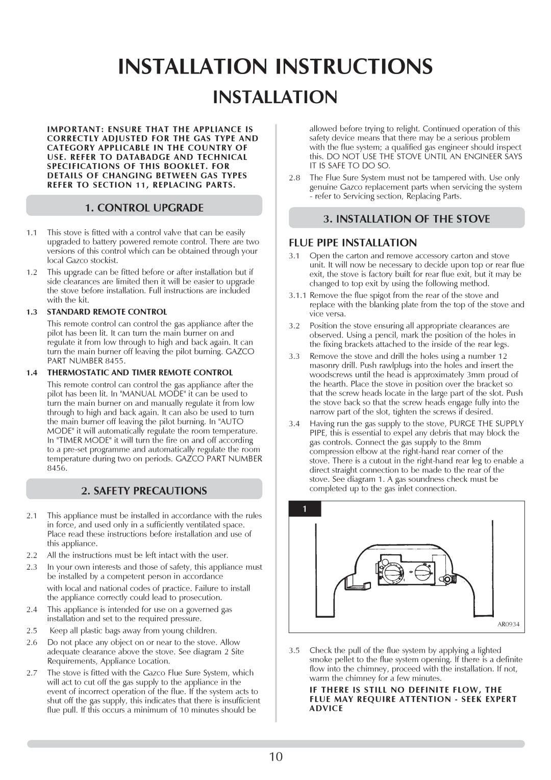
Another significant characteristic of the Stovax Stove Range is its robust construction. Each stove is crafted from high-quality materials, ensuring durability and longevity. The cast iron bodies provide excellent heat retention, so the warmth radiates even after the fire has dwindled, making these stoves not only beautiful but also practical.
Moreover, many of the Stovax stoves come with the option of a contemporary or traditional log store, enhancing both storage and design aesthetics. The easily accessible storage compartment allows for convenient firewood management, ensuring you can keep the home toasty without the hassle of frequent trips outside.
Stovax also offers a range of accessories and enhancements, including flue systems and chimney liners, ensuring a seamless installation and optimal performance tailored to your specific home requirements. This attention to detail exemplifies Stovax's dedication to customer satisfaction.
In summary, the Stovax Stove Range delivers on multiple fronts, combining advanced technology, aesthetic versatility, robust construction, and thoughtful features. A Stovax stove not only promises warmth but also elevates the charm and elegance of your living space, making it a worthwhile investment for any homeowner seeking comfort and style.