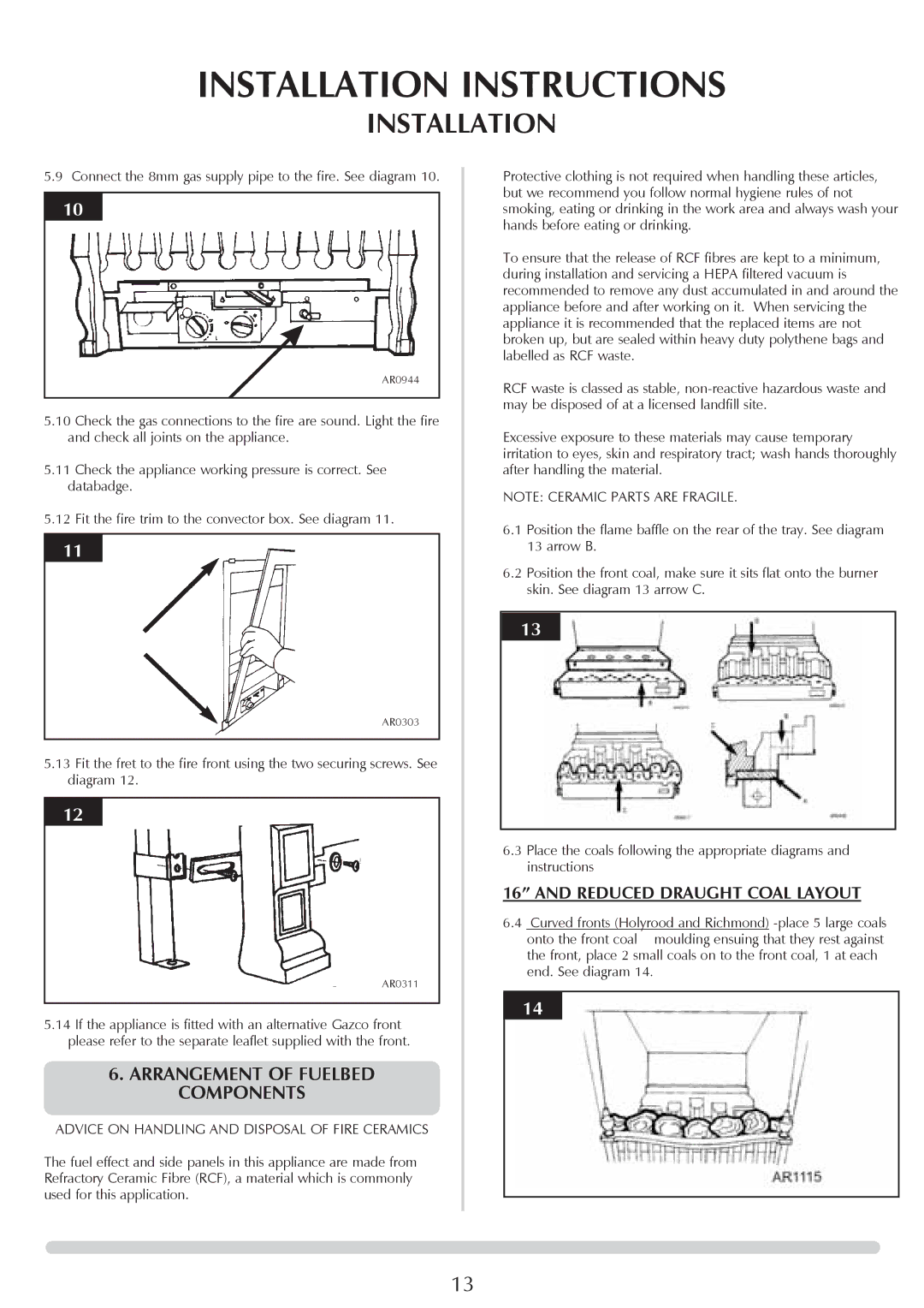
VFC Radiant & Convector Fire Range specifications
The Stovax VFC Radiant & Convector Fire Range embodies the pinnacle of contemporary fireplace design, marrying aesthetics with cutting-edge technology. This range is meticulously crafted to deliver warmth and style to any living space, ensuring an inviting atmosphere for families and guests alike.One of the standout features of the VFC range is its dual-mode operation. The Radiant fires radiate heat directly into the room, creating immediate warmth, while the Convector models utilize advanced convection technology to circulate heated air throughout the space. This dual functionality allows homeowners to choose their preferred heating method, ensuring comfort during cold weather.
Energy efficiency is a cornerstone of the VFC range, designed with modern living in mind. The VFC fireplaces boast impressive efficiency ratings, meaning they convert a greater proportion of wood fuel into usable heat. This not only reduces fuel consumption but also minimizes emissions, making it a more environmentally friendly choice compared to traditional stoves.
Built from high-quality materials, the VFC range showcases a robust steel body paired with a cast iron door, ensuring durability and longevity. The range is also available in various sizes and styles, accommodating different room dimensions and personal tastes. Each model can be customized with a selection of trims and finishes that seamlessly integrate with a variety of interior decors.
The technology behind the VFC also includes a user-friendly air control system, enabling precise regulation of the burn rate. This feature contributes to optimal fuel efficiency and ensures a clean, environmentally friendly burn. Additionally, the large glass viewing window not only enhances the aesthetic appeal but also allows for a captivating view of the flames, adding to the ambiance of your room.
Moreover, installation is straightforward with the VFC range, which is designed to be compatible with existing flues and chimneys. Homeowners can enjoy a hassle-free setup while still benefiting from the advanced heating technologies.
In summary, the Stovax VFC Radiant & Convector Fire Range offers a compelling combination of modern technology, efficiency, and elegance. Its versatile heating options, environmentally-friendly design, and customizability make it an ideal choice for anyone looking to enhance their home’s comfort and style. Whether you’re curling up with a book or entertaining friends, the VFC range promises to create a warm and inviting centerpiece for your living space.

