STUDER INNOTEC | COMPACT |
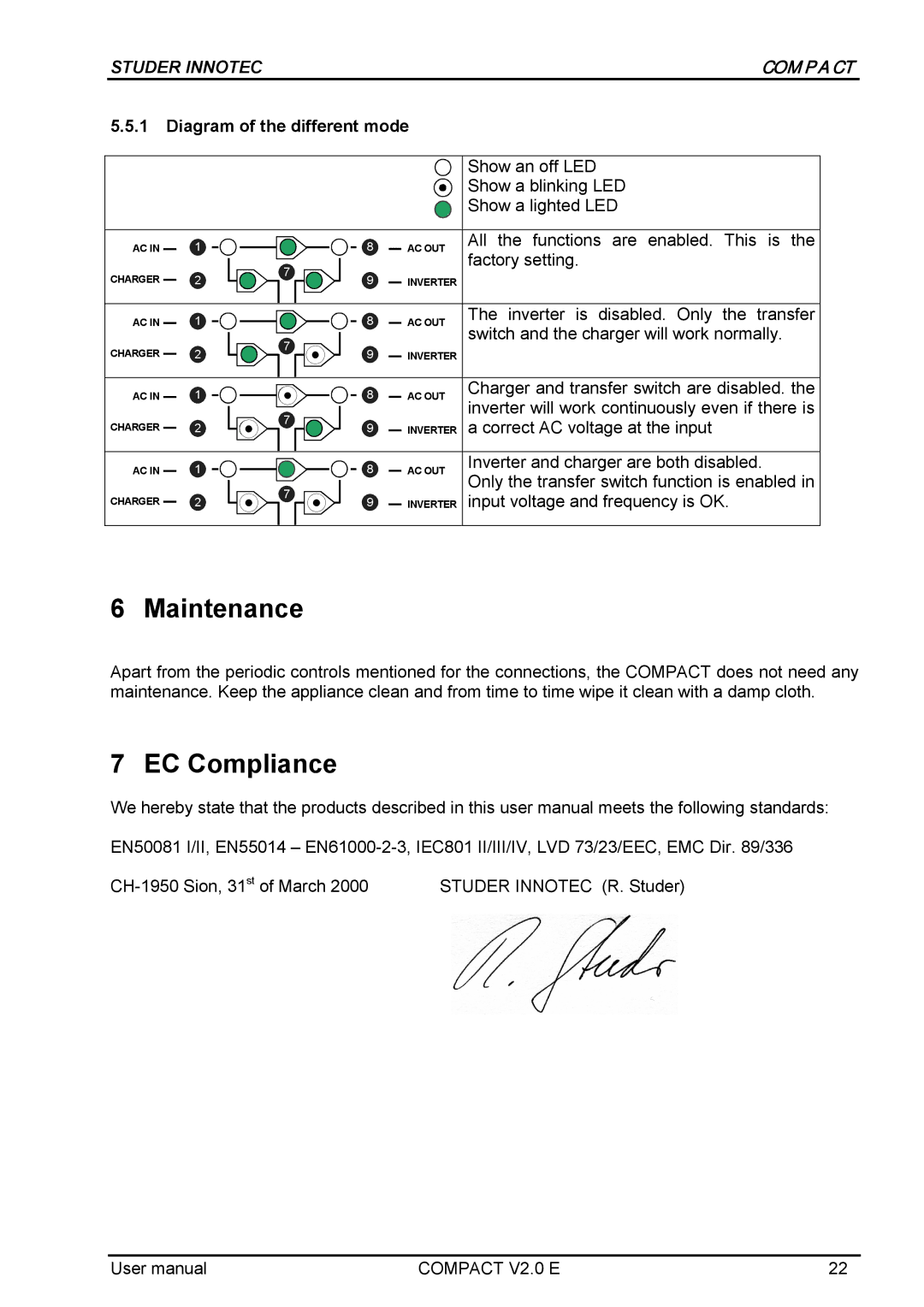
5.5.1Diagram of the different mode
|
|
|
|
|
|
|
|
| Show an off LED |
|
|
|
|
|
|
|
|
| Show a blinking LED |
|
|
|
|
|
|
|
|
| Show a lighted LED |
|
|
|
|
|
|
|
|
|
|
AC IN |
| 1 |
| 8 |
|
|
| AC OUT | All the functions are enabled. This is the |
|
|
| |||||||
|
|
| 7 |
|
|
|
|
| factory setting. |
CHARGER |
| 2 | 9 |
|
|
| INVERTER |
| |
|
|
|
|
|
| ||||
|
|
|
|
|
|
|
|
|
|
AC IN |
| 1 |
| 8 |
|
|
| AC OUT | The inverter is disabled. Only the transfer |
CHARGER |
| 2 | 7 | 9 |
|
|
| INVERTER | switch and the charger will work normally. |
|
|
|
|
| |||||
|
|
|
|
|
| ||||
|
|
|
|
|
|
|
|
|
|
AC IN |
| 1 |
| 8 |
|
|
| AC OUT | Charger and transfer switch are disabled. the |
|
|
|
|
| |||||
|
|
| 7 |
|
|
|
|
| inverter will work continuously even if there is |
CHARGER |
| 2 | 9 |
|
|
| INVERTER | a correct AC voltage at the input | |
|
|
|
|
| |||||
|
|
|
|
|
|
|
|
|
|
AC IN |
| 1 |
| 8 |
|
|
| AC OUT | Inverter and charger are both disabled. |
| 7 |
|
|
| Only the transfer switch function is enabled in | ||||
|
|
|
|
|
|
|
| ||
CHARGER |
| 2 | 9 |
|
|
| INVERTER | input voltage and frequency is OK. | |
|
|
|
|
| |||||
|
|
|
|
|
|
|
|
|
|
6 Maintenance
Apart from the periodic controls mentioned for the connections, the COMPACT does not need any maintenance. Keep the appliance clean and from time to time wipe it clean with a damp cloth.
7 EC Compliance
We hereby state that the products described in this user manual meets the following standards:
EN50081 I/II, EN55014 –
STUDER INNOTEC (R. Studer) |
User manual | COMPACT V2.0 E | 22 |
