STUDER INNOTEC | COMPACT |
the OUTPUT less it’s give to the charger. Priority to the OUTPUT. When the power sharing is used the LED 200% (red) is lit to point out that’s the charge is limited.
Caution: If the power use on the OUTPUT is higher than the value of the INPUT LIMIT (26) the COMPACT limits the current, then the generator means to stop or the circuit breaker before means to break.
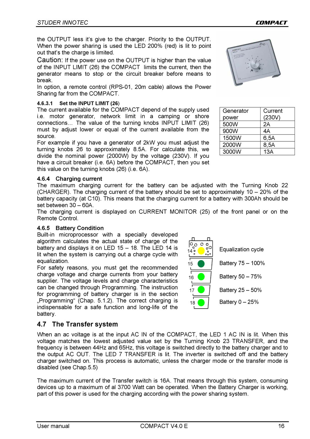
In option, a remote control
4.6.3.1Set the INPUT LIMIT (26)
The current available for the COMPACT depend of the supply used i.e. motor generator, network limit in a camping or shore connections… The value of the turning knobs INPUT LIMIT (26) must by adjust lower or equal of the current available from the source.
For example if you have a generator of 2kW you must adjust the turning knobs 26 to approximately 8.5A. For calculate this, we divide the nominal power (2000W) by the voltage (230V). If you have a circuit breaker (i.e. 6A) before the COMPACT, then you set this value on the turning knobs (26) (i.e. 6A).
4.6.4Charging current
Generator | Current |
power | (230V) |
500W | 2A |
900W | 4A |
1500W | 6,5A |
2000W | 8,5A |
3000W | 13A |
The maximum charging current for the battery can be adjusted with the Turning Knob 22 (CHARGER). The charging current of the battery should be set to approximately 10 – 20% of the battery capacity (at C10). This means that the charging current for a battery with 300Ah should be set between 30 – 60A.
The charging current is displayed on CURRENT MONITOR (25) of the front panel or on the Remote Control.
4.6.5Battery Condition
For safety reasons, you must get the recommended charge voltage and charge currents from your battery supplier. The voltage levels and charge characteristics can be changed through Programming. The instruction for programming of battery charger is in the section „Programming“ (Chap. 5.1.2). The correct charging is indispensable for a safe function and
14 | Equalization cycle | |
15 | Battery 75 | – 100% |
16 | Battery 50 | – 75% |
17 | Battery 25 | – 50% |
18 | Battery 0 – 25% | |
4.7 The Transfer system
When an ac voltage is at the input AC IN of the COMPACT, the LED 1 AC IN is lit. When this voltage matches the lowest adjusted value set by the Turning Knob 23 TRANSFER, and the frequency is between 44Hz and 65Hz, this voltage is switched directly to the battery charger and to the output AC OUT. The LED 7 TRANSFER is lit. The inverter is switched off and the battery charger switched on. This process is automatic, unless the charger mode or the transfer mode is disabled (see Chap.5.5)
The maximum current of the Transfer switch is 16A. That means through this system, consuming devices up to a maximum of al 3700 Watt can be operated. When the Battery Charger is working, part of this power is used for the charging according with the power sharing system.
User manual | COMPACT V4.0 E | 16 |