Connection | Wire Color |
Neutral (N) | Light Blue |
Line (L) | Brown |
Earth/Ground (E) | Green/Yellow |
Safety Warning: The Model 46 does not contain an AC mains disconnect switch. As such, the AC mains cord plug serves as the disconnection de- vice. Safety considerations require that the plug and associated inlet be easily accessible to allow rapid disconnec- tion of AC mains power should it prove necessary.
As soon as AC mains power is applied the Model 46 will begin its
Configuration
For the Model 46 to support the needs of specific applications a number of operat- ing parameters must be configured. These include the
Configuration – Interface 1 and 2
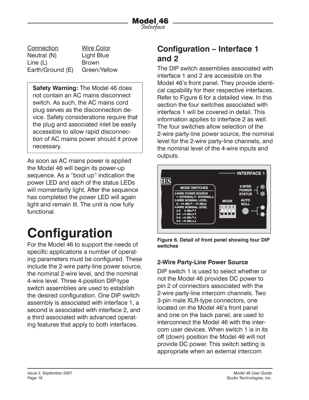
The DIP switch assemblies associated with interface 1 and 2 are accessible on the Model 46’s front panel. They provide identi- cal capability for their respective interfaces. Refer to Figure 6 for a detailed view. In this section the four switches associated with interface 1 will be covered in detail. This information applies to interface 2 as well. The four switches allow selection of the
Figure 6. Detail of front panel showing four DIP switches
2-Wire Party-Line Power Source
DIP switch 1 is used to select whether or not the Model 46 provides DC power to pin 2 of connectors associated with the
Issue 2, September 2007 | Model 46 User Guide |
Page 16 | Studio Technologies, Inc. |