is part number
It’s important to ensure that the source of the remote control signals can meet the Model 46’s
for 30 milliseconds, then a minimum no- current period of 30 milliseconds, followed by current flow for a minimum of 30 milli- seconds. The second period of current flow must come within one second of the start of the first.
Once the interconnect method and the source of the control signals have been selected, refer to Figure 4 for connection details. Ensure that the connected signals follow the specified polarity or damage to the
| ||
Function | Header (P9) | Interface Cable |
|
|
|
Remote Auto Null Interface 1 + | 7 | 4 |
|
|
|
Remote Auto Null Interface 1 – | 9 | 5 |
|
|
|
Remote Auto Null Interface 2 + | 2 | 6 |
|
|
|
Remote Auto Null Interface 1 – | 4 | 7 |
|
|
|
Remote “Mic Kill” + | 6 | 8 |
|
|
|
Remote “Mic Kill” – | 8 | 9 |
|
|
|
Figure 4. Remote control input pin-out chart
It’s important that a competent techni- cian be available to perform the actual remote control input connection process. As expected, mating the interconnecting cable assembly with the Model 46’s 10- pin “header” requires removing the unit’s cover. As such, this must be done only after confirming that all sources of mains power have been disconnected from the unit.
AC Mains Power
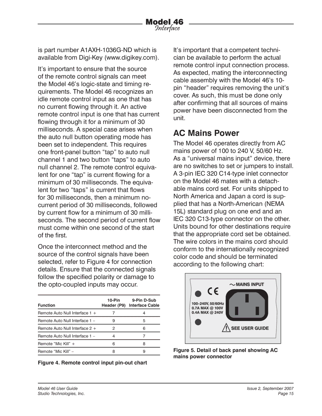
The Model 46 operates directly from AC mains power of 100 to 240 V, 50/60 Hz. As a “universal mains input” device, there are no switches to set or jumpers to install. A
Figure 5. Detail of back panel showing AC mains power connector
Model 46 User Guide | Issue 2, September 2007 |
Studio Technologies, Inc. | Page 15 |
