A s s e m b l y I n s t r u c t i o n s ![]()
![]()
![]()
![]()
![]()
![]()
![]()
![]()
![]()
![]()
![]()
![]()
![]()
![]()
5
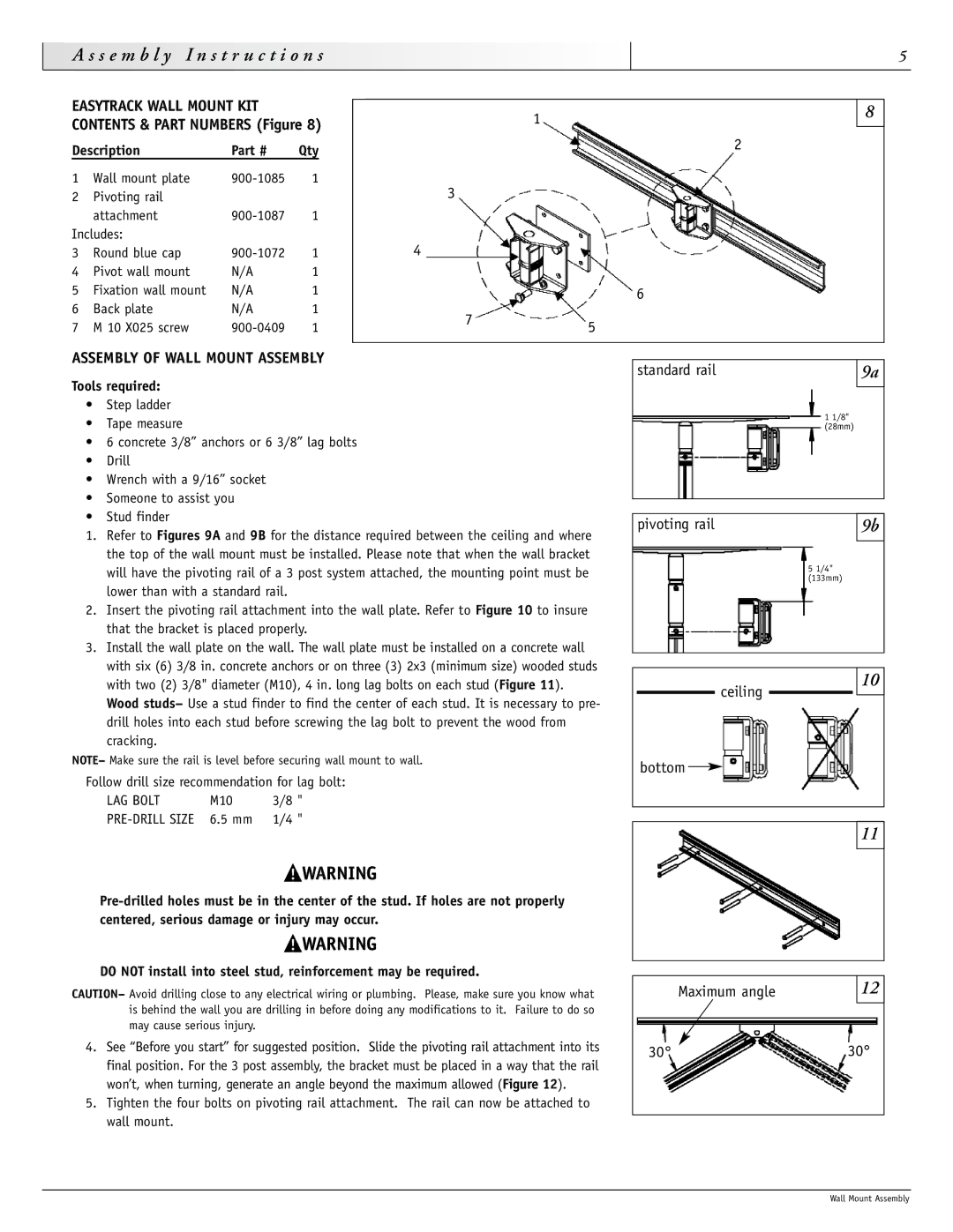
EASYTRACK WALL MOUNT KIT CONTENTS & PART NUMBERS (Figure 8)
Description | Part # | Qty | |
1 | Wall mount plate | 1 | |
2 | Pivoting rail |
|
|
| attachment | 1 | |
Includes: |
|
| |
3 | Round blue cap | 1 | |
4 | Pivot wall mount | N/A | 1 |
5 | Fixation wall mount | N/A | 1 |
6 | Back plate | N/A | 1 |
7 | M 10 X025 screw | 1 | |
1
2
3
4
6
75
8
ASSEMBLY OF WALL MOUNT ASSEMBLY
Tools required:
•Step ladder
•Tape measure
•6 concrete 3/8” anchors or 6 3/8” lag bolts
•Drill
•Wrench with a 9/16” socket
•Someone to assist you
•Stud finder
1.Refer to Figures 9A and 9B for the distance required between the ceiling and where the top of the wall mount must be installed. Please note that when the wall bracket will have the pivoting rail of a 3 post system attached, the mounting point must be lower than with a standard rail.
2.Insert the pivoting rail attachment into the wall plate. Refer to Figure 10 to insure that the bracket is placed properly.
3.Install the wall plate on the wall. The wall plate must be installed on a concrete wall with six (6) 3/8 in. concrete anchors or on three (3) 2x3 (minimum size) wooded studs with two (2) 3/8" diameter (M10), 4 in. long lag bolts on each stud (Figure 11). Wood studs– Use a stud finder to find the center of each stud. It is necessary to pre- drill holes into each stud before screwing the lag bolt to prevent the wood from cracking.
NOTE– Make sure the rail is level before securing wall mount to wall.
Follow drill size recommendation for lag bolt:
LAG BOLT | M10 | 3/8 " |
standard rail | 9a |
|
|
1 1/8" (28mm)
pivoting rail | 9b |
|
|
5 1/4" (133mm)
10
ceiling
bottom 
DO NOT install into steel stud, reinforcement may be required.
CAUTION– Avoid drilling close to any electrical wiring or plumbing. Please, make sure you know what is behind the wall you are drilling in before doing any modifications to it. Failure to do so may cause serious injury.
4.See “Before you start” for suggested position. Slide the pivoting rail attachment into its final position. For the 3 post assembly, the bracket must be placed in a way that the rail won’t, when turning, generate an angle beyond the maximum allowed (Figure 12).
5.Tighten the four bolts on pivoting rail attachment. The rail can now be attached to wall mount.
11
Maximum angle |
| 12 |
|
|
|
30° | 30° | |
|
|
|
Wall Mount Assembly