6 | I n s t a l l a t i o n | ||||||
4. Install the both left and right retaining pins into |
|
|
|
|
|
|
|
the |
|
|
|
|
|
| F |
plate(E), upper connector(A) and into the back |
|
|
|
|
|
|
|
shell receiver(D) Figure 7. | +2 0 | 2 | 4 | 6 | 8 10 |
| |
5. Adjust back shell to be centered between side |
|
|
|
| 12 | ||
+3 +1 |
|
|
|
|
| ||
1 | 3 | 5 | 7 |
|
| ||
plates (G) |
|
|
| 9 11 | |||
|
|
|
|
| |||
|
|
|
|
|
|
| |
6. Tighten both upper connector fasteners (H) while |
|
|
|
|
|
|
|
gently holding the upper connector inward |
|
|
|
|
|
|
|
towards the center of the chair. | Figure 8 |
|
|
|
| ||
7.Tighten both lower connector fasteners (I).
8.Back shell should rotate freely on pins and be easily removable.
NOTE– Important: Ensure that the back shell rotates freely and that the upper connectors do not hit the side plates. If required, adjust the side plate angle to achieve smooth operation.
H | H |
|
I | I |
|
| G |
|
| Figure 9 | Figure 10 |
 I n s t a l l a t i o n


 7
7
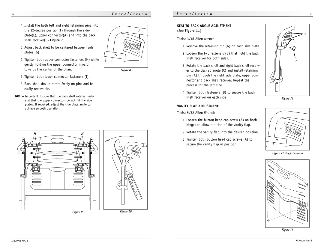
SEAT TO BACK ANGLE ADJUSTMENT (See Figure 11)
B
Tools: 3/16 Allen wrench
1. Remove the retaining pin (A) on each side plate.
2. Loosen the two fasteners (B) that hold the back |
|
shell receiver for both sides. | A |
|
3.Rotate the back shell and right back shell receiv- er to the desired angle (C) and install retaining pin (A) through the right side plate, upper con-
nector and back shell receiver. Repeat the process for the left side.
4. Tighten both fasteners (B) to secure the back |
|
shell receiver on each side | Figure 11 |
|
VANITY FLAP ADJUSTMENT: |
|
|
|
|
|
|
|
Tools: 5/32 Allen Wrench |
|
|
|
|
|
|
|
1. Loosen the button head cap screw (A) on both |
|
|
|
|
|
|
|
hinges to allow rotation of the vanity flap. | +2 0 | 2 | 4 |
|
|
|
|
C |
| 6 8 10 | 12 | ||||
2. Rotate the vanity flap into the desired position. | +3 +1 |
|
|
|
|
| |
1 | 3 | 5 |
|
|
| ||
|
|
| 7 |
|
| ||
|
|
|
| 9 11 | |||
3. Tighten both button head cap screws (A) to |
|
|
|
|
| ||
|
|
|
|
|
|
| |
secure the vanity flap in position. |
|
|
|
|
|
|
|
Figure 12 Angle Positions | |||||||
A |
Figure 13
XT200005 Rev. B | XT200005 Rev. B |