34 | I X . S e t - U p , A d j u s t m e n t & U s e | |
2. | Back Angle Adjustment on Seat Frame |
|
| a. Remove the front securing bolt (C) on the side of |
|
| the backrest hinge plate. |
|
| b. Loosen the lower rear bolt (D) |
|
| c. Set at desired angle. There are five holes (in 4º | D |
| increments) to choose from. | C |
|
| |
| d. Reinstall the front bolt and tighten both bolts |
|
| securely. |
|
L. 12" DRIVE WHEEL |
| |
Drive Wheel Position Adjustment |
| |
I X . S e t - U p , A d j u s t m e n t & U s e | 35 |
MANUAL WHEELCHAIR CONVERSION KIT |
|
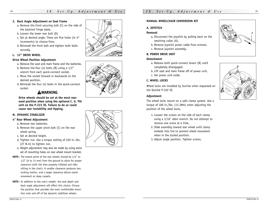
A. JOYSTICK |
|
Removal | A |
a. Disconnect the joystick by pulling back on the |
|
retaining collar (A). |
|
b. Remove joystick power cable from armrest. |
|
c. Remove joystick assembly. |
|
B. POWER DRIVE UNIT |
|
Detachment
a. Remove the seat and main frame and the batteries. b. Remove the four (4) bolts (B) using a 1/2"
wrench from each
c. Move the socket forward or backwards to the desired position.
d. Reinstall the four (4) bolts in the
Drive wheels should be set at the most rear- ward position when using the optional C. G. Tilt unit on the
B |
a. Release both
b. Lift seat and main frame off of power unit. c. Set power unit aside.
C. WHEEL LOCKS
Wheel locks are installed by Sunrise when requested on the Quickie
Adjustment
The wheel locks mount on a split clamp system. Use a torque of 100 in./lbs. (11.3Nm) when adjusting the position of the wheel locks.
B |
M. DYNAMIC STABILIZER
4" Rear Wheel Adjustment a. Remove rear batteries.
b. Remove the upper pivot bolt (C) on the rear wheel spring.
c. Set at desired height.
d. Tighten nut. Use a torque setting of 240
e. Height adjustment may also be made by using extra set of mounting holes on rear wheel mount bracket.
C |
1.Loosen the screws on the side of each clamp using a 3/16" allen wrench. Do not attempt to remove one screw at a time.
2.Slide assembly toward rear wheel until clamp embeds into tire to prevent wheel movement when in the locked position.
3.Adjust angle position. Tighten screws.
NOTE– The lowest point of the rear wheels should be 1/4" to 1/2" (6 to 13 mm) from the ground to allow for proper clearance (with the tires properly inflated and rider sitting in the chair). A smaller clearance produces less rocking motion, and a larger clearance allows easier movement on deep carpets.
NOTE– In addition to the user’s weight, the seat depth and back angle adjustment will effect this choice. Choose the position that provides the most comfortable transi- tion onto and off of the dynamic stabilizer wheels.
930476 Rev. A | 930476 Rev. A |