Floppy Drive Connector
Pin Definitions

Chapter 2: Installation

2-9 Floppy Drive, SIMLP, Serial ATA and Hard Disk Drive Connections

COM1 USB0/1

Note the following when connecting the floppy and hard disk drive cables:

The floppy disk drive cable has seven twisted wires.

A red mark on a wire typically designates the location of pin 1.

A single floppy disk drive ribbon cable has 34 wires and two connectors to provide for two floppy disk drives. The connector with twisted wires always connects to drive A, and the connector that does not have twisted wires always

connects to drive B.


Pin#

Definition

Pin #

Definition


1

Ground

2

FDHDIN


3

Ground

4

Reserved


5

Key

6

FDEDIN

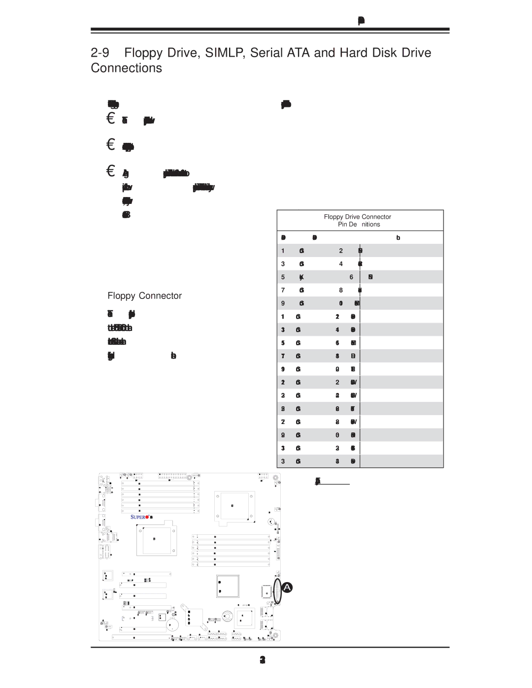
Floppy Connector


7

Ground

8

Index


9

Ground

10

Motor Enable


The floppy connector is located close

11

Ground

12

Drive Select B

to the Front Panel Control on the

13

Ground

14

Drive Select B

motherboard. See the table on the

15

Ground

16

Motor Enable

right for pin definitions.

17

Ground

18

DIR


19

Ground

20

STEP


21

Ground

22

Write Data


23

Ground

24

Write Gate


25

Ground

26

Track 00


27

Ground

28

Write Protect


29

Ground

30

Read Data


31

Ground

32

Side 1 Select


33

Ground

34

Diskette

KB/Mouse

Fan5

Fan6

JPW3

J6


A. Floppy


JPW2

JPW1


P2 DIMM3A


Fan1


USB2/3


P2 DIMM3B


P2 DIMM2A


P2 DIMM2B


P2 DIMM1A


CPU1


P2 DIMM1B


Fan7/CPU1


COM2

Fan8/CPU2 Fan

X8DA3/i


LAN1

LAN2

CPU2


AUDIO


P1 DIMM1B

P1 DIMM1A

P1 DIMM2B

P1 DIMM2A

P1 DIMM3B

P1 DIMM3A

SP1

LE1

JOH1

JD1

Fan2


JF1


82573V

Slot6 PCI-E x16


LAN


CTRL

JPL1

1

JI2C3


JI2C4


Intel IOH-36D


Slot5 PCI 33MH


82573L

JPL2


(North Bridge)


LAN

Slot4 PCI 33MH


CTRL


JI2C1


JI2C2


BIOS


LES2

LES1


Slot3 PCI-E X16


1394_2 1394_1

JPI1

SPI


ICH10R


1394

JBT1


Intel

I-Button

1068E

JC2

Slot2 PCI-E X4


CTRL


South


SAS CTRL


Bridge

T-SGPIO2 T-SGPIO1


Battery


CD1

Slot1 PCI 33MH


I-SATA5 I-SATA3

I-SATA1


USB6/7 USB4/5

USB9

USB8


Slot0 SIMLC


I-SATA4 I-SATA2

I-SATA0

JWD1JL1


JUSB3

JUSB2


Fan3


S I/O

Floppy

A


J5

JFDD1


JSM2

SAS 4~7


JSM1

SAS 0~3


JWOL1


JPS1JPS2


Fan4


2-31

Page 51
Image 51
SUPER MICRO Computer X8DA3 user manual Floppy Connector, floppy connector is located close, To the Front Panel Control on

X8DA3 specifications

Super Micro Computer, also known as Supermicro, is a prominent player in the world of computing hardware, particularly known for its high-performance server solutions. One of their noteworthy offerings is the X8DA3 motherboard, which is designed for dual-processor systems and caters to various applications, including data centers, cloud computing, and enterprise-level operations.

The Supermicro X8DA3 motherboard supports Intel's Nehalem and Westmere architectures, accommodating two LGA 1366 sockets for Intel Xeon processors. This setup allows for impressive computational power and scalability. The motherboard can support up to 192GB of DDR3 RAM across six DIMM slots, enabling high memory bandwidth essential for memory-intensive applications.

One of the standout features of the X8DA3 is its robust I/O options. It comes equipped with six SATA II ports and two SAS ports, allowing for flexible storage configurations. Additionally, the board supports a range of RAID levels, including 0, 1, 5, and 10, providing data redundancy and performance optimization. For enhanced connectivity, the motherboard includes dual Gigabit Ethernet ports, ensuring reliable networking capabilities which are crucial for server environments.

In terms of expandability, the X8DA3 features multiple PCIe slots, providing users with the ability to add various expansion cards such as graphics cards, network cards, or additional storage controllers. This flexibility allows companies to tailor their server setups according to specific needs.

Power management is another critical aspect of the X8DA3. It supports ATX power supplies and features advanced power-saving technologies that help in reducing overall energy consumption. This ecological consideration is particularly important for organizations looking to minimize their carbon footprint while maintaining optimal performance.

For thermal management, Supermicro incorporates a design that allows for efficient airflow and cooling, which is crucial for maintaining system stability during intensive workloads. The motherboard is also equipped with multiple temperature sensors that provide real-time monitoring, ensuring components operate within safe thermal levels.

Overall, the Super Micro Computer X8DA3 motherboard is a reliable and high-performance choice for businesses requiring a versatile and powerful computing platform. Its support for dual processors, extensive memory options, advanced storage capabilities, and solid expandability make it an attractive option for enterprise applications in today’s computationally demanding environments.