Step 9. Checking the System – With gas line installed run initial system checkout before closing up the front of the unit. Follow the pilot lighting instructions on page 15.

Note: Instructions are also found on the pull out panel located on the bottom surface of the appliance.

When first lighting the appliance, it will take a few minutes for the line to purge itself of air. Once purging is complete, the pilot and burner will light and operate as indicated in the instruc- tion manual. Subsequent lightings of the appli- ance will not require such purging. Inspect the pilot flame (remove logs, if necessary, handling carefully).

The pilot flame should be steady, not lifting or floating. Flame should be blue in color with traces of orange at the outer edge.

The top ³⁄₈" (10 mm) at the pilot generator (thermocouple) should be engulfed in the pilot flame (NG only).

Replace logs if removed for pilot inspection.

To light the burner; turn “ON” the optional remote wall switch (if installed) and rotate the gas valve control knob counterclockwise to the “ON” position.

Step 10. Installing the Screen Panel Assem- bly – Retrieve the screen door frame. Position the door frame in front of the firebox opening in the brackets at the base of the fireplace front opening. Lean the door frame back towards the fireplace ensuring that the frame seats evenly as it draws shut.

Install the three (3) ¹⁄₄"-20 x 1" Phillips pan head screws removed previously and tighten to secure.

Installing the Optional Glass Door

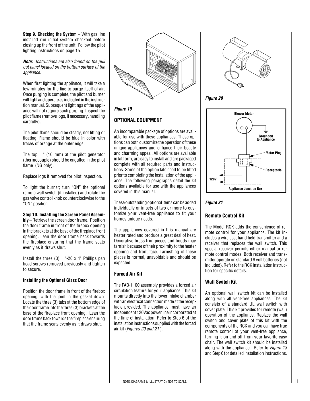
Position the door frame in front of the firebox opening, with the joint in the gasket down. Locate the three (3) tabs at the bottom edge of the door frame into the three (3) brackets at the base of the fireplace front opening. Lean the door frame back towards the fireplace ensuring that the frame seats evenly as it draws shut.

Figure 19

OPTIONAL EQUIPMENT

An incomparable package of options are avail- able for use with these appliances. These op- tions can both customize the operation of these unique appliances and enhance their beauty and charming appeal. All options are available in kit form, are easy to install and are packaged complete with all required parts and instruc- tions. Some of the option kits need to be fitted prior to completing the installation of the appli- ance. The following paragraphs detail the kit options available for use with the appliances covered in this manual.

These outstanding optional items can be added individually or in sets of two or more to cus- tomize your vent-free appliance to fit your homes unique needs.

The appliances covered in this manual are heater rated and produce a great deal of heat. Decorative brass trim pieces and hoods may tarnish because of their proximity to the heater opening and front face. Tarnishing of these pieces is normal, unavoidable and should be expected.

Forced Air Kit

The FAB-1100 assembly provides a forced air circulation feature for your appliance. This kit mounts directly into the lower intake chamber with an electrical connection made at the recep- tacle provided. The appliance must have an independent 120Vac power line incorporated at the time of installation. Refer to Step 6 of the installation instructions supplied with the forced air kit (Figures 20 and 21 ).

NOTE: DIAGRAMS & ILLUSTRATION NOT TO SCALE.

Figure 20

Blower Motor

Grounded

to Appliance

Motor Plug

Receptacle

120V

Appliance Junction Box

Figure 21

Remote Control Kit

The Model RCK adds the convenience of re- mote control for your appliance. The kit in- cludes a wireless, hand held transmitter and a receiver that replaces the wall switch. This special receiver permits either manual or re- mote control modes. Both receiver and trans- mitter operate on standard 9 volt batteries (not included). Refer to the RCK installation instruc- tion for specific details.

Wall Switch Kit

An optional wall switch kit can be installed along with all vent-free appliances. The kit consists of a standard UL wall switch with cover plate. This kit provides for remote (wall) operation of the appliance. Replace the wall switch and cover plate of this kit with the components of the RCK and you can have true remote control of your vent-free appliance, turning it on and off from your favorite easy chair. The wall switch kit should be installed along with the appliance. Refer to Figure 13 and Step 6 for detailed installation instructions.

11

Page 11
Image 11
Superior VFPF-CMN-2, VFST-CMP-2, VFPF-CMP-2 Optional Equipment, Forced Air Kit, Remote Control Kit, Wall Switch Kit

VFPF-CMP-2, VFPF-CMN-2, VFST-CMN-2, VFST-CMP-2 specifications

The Superior VFST-CMP-2, VFPF-CMN-2, VFPF-CMP-2, and VFST-CMN-2 represent a cutting-edge suite of products designed to meet the demands of modern applications in various industries, including telecommunications, data management, and industrial automation. Each of these models incorporates advanced features and technologies aimed at enhancing performance, reliability, and user experience.

The VFST-CMP-2 is particularly focused on high-speed data processing. With an impressive throughput and low latency, it is engineered for tasks that require rapid data handling, making it suitable for applications in cloud computing and data centers. This model incorporates state-of-the-art error correction algorithms, ensuring data integrity during transmission and significantly reducing downtime.

In contrast, the VFPF-CMN-2 is tailored for network management and monitoring. It boasts a comprehensive interface that allows users to track network performance in real-time. The intuitive dashboard provides insights into traffic loads, bottlenecks, and overall system health. This model is equipped with cutting-edge analytics features that leverage machine learning to predict potential issues before they become critical, enhancing proactive maintenance capabilities.

The VFPF-CMP-2 combines features from both offerings, positioned as a hybrid solution that caters to versatile applications. It balances powerful data processing and efficient network management, making it an optimal choice for organizations looking to streamline operations across various platforms. With its modular architecture, users can easily scale their systems as demand increases without significant overhauls.

Finally, the VFST-CMN-2 excels in interoperability. Designed to integrate seamlessly with existing infrastructures, it supports a wide range of protocols and standards. This flexibility ensures that it can be deployed in diverse environments, minimizing compatibility issues. The device also emphasizes security, incorporating advanced encryption technologies to protect sensitive data during transmission.

In summary, the Superior VFST-CMP-2, VFPF-CMN-2, VFPF-CMP-2, and VFST-CMN-2 are exemplary models that bring together innovative features and technologies. Their unique characteristics make them well-suited for various applications, providing essential tools for enhanced data processing, network management, and operational efficiency. Organizations investing in these products are poised to benefit from improved performance and adaptability in an ever-evolving technological landscape.