System Sensor smoke detectors are marked with a compat- ible identifier located as the last digit of a five digit code stamped on the back of the product. Connect detectors only to compatible control units as indicated in System Sensor’s compatibility chart which contains a current list of UL- listed compatible control units and detectors. A copy of this list is available from System Sensor upon request.
Wire connections are made by stripping about 1/4 inch of insulation from the end of the feed wire, inserting the wire into the appropriate terminal, and tightening the screw to secure the wire in place.
Installation
![]()
![]() WARNING
WARNING
Remove power from the control unit or initiating device cir- cuits before installing detectors.
1.Wire the
2.Align the arrows on the detector with the arrows on the mounting bracket.
3.Turn the detector clockwise in the mounting bracket un- til it clicks into place.
4.After all detectors have been installed, apply power to the control unit or initiating device circuits.
5.Test the detector as described in TESTING.
6.Reset the detector at the system control panel.
7.Notify the proper authorities the system is in operation.
![]()
![]() CAUTION
CAUTION
Dust covers are an effective way to limit the entry of dust into smoke detector sensing chambers. However, they may not completely prevent airborne dust particles from enter- ing the detector. Therefore, System Sensor recommends the removal of detectors before beginning construction or other dust producing activity. Be sure to remove dust covers from any sensors that were left in place during construction as part of returning the system to service.
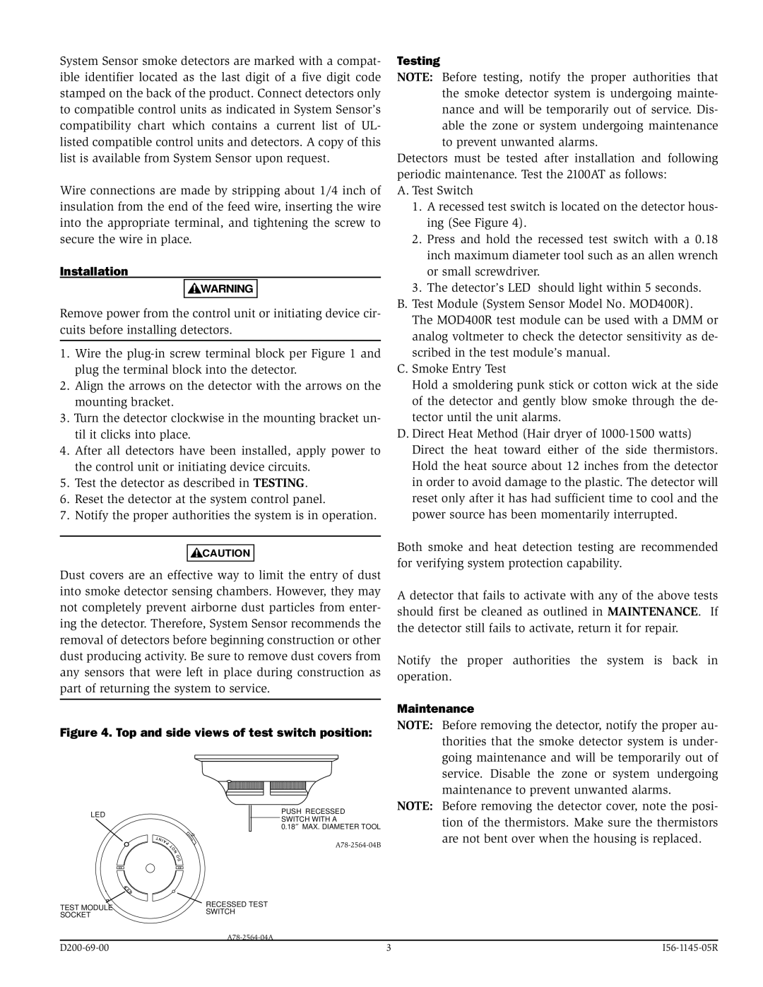
Figure 4. Top and side views of test switch position:
LED | PUSH RECESSED | |
SWITCH WITH A | ||
| ||
| 0.18″ MAX. DIAMETER TOOL | |
| ||
TEST MODULE | RECESSED TEST | |
SWITCH | ||
SOCKET | ||
|
Testing
NOTE: Before testing, notify the proper authorities that the smoke detector system is undergoing mainte- nance and will be temporarily out of service. Dis- able the zone or system undergoing maintenance to prevent unwanted alarms.
Detectors must be tested after installation and following periodic maintenance. Test the 2100AT as follows:
A. Test Switch
1.A recessed test switch is located on the detector hous- ing (See Figure 4).
2.Press and hold the recessed test switch with a 0.18 inch maximum diameter tool such as an allen wrench or small screwdriver.
3.The detector’s LED should light within 5 seconds.
B.Test Module (System Sensor Model No. MOD400R). The MOD400R test module can be used with a DMM or analog voltmeter to check the detector sensitivity as de- scribed in the test module’s manual.
C.Smoke Entry Test
Hold a smoldering punk stick or cotton wick at the side of the detector and gently blow smoke through the de- tector until the unit alarms.
D.Direct Heat Method (Hair dryer of
Both smoke and heat detection testing are recommended for verifying system protection capability.
A detector that fails to activate with any of the above tests should first be cleaned as outlined in MAINTENANCE. If the detector still fails to activate, return it for repair.
Notify the proper authorities the system is back in operation.
Maintenance
NOTE: Before removing the detector, notify the proper au- thorities that the smoke detector system is under- going maintenance and will be temporarily out of service. Disable the zone or system undergoing maintenance to prevent unwanted alarms.
NOTE: Before removing the detector cover, note the posi- tion of the thermistors. Make sure the thermistors are not bent over when the housing is replaced.
3 |