
2451TH, 2451, 2451TH specifications
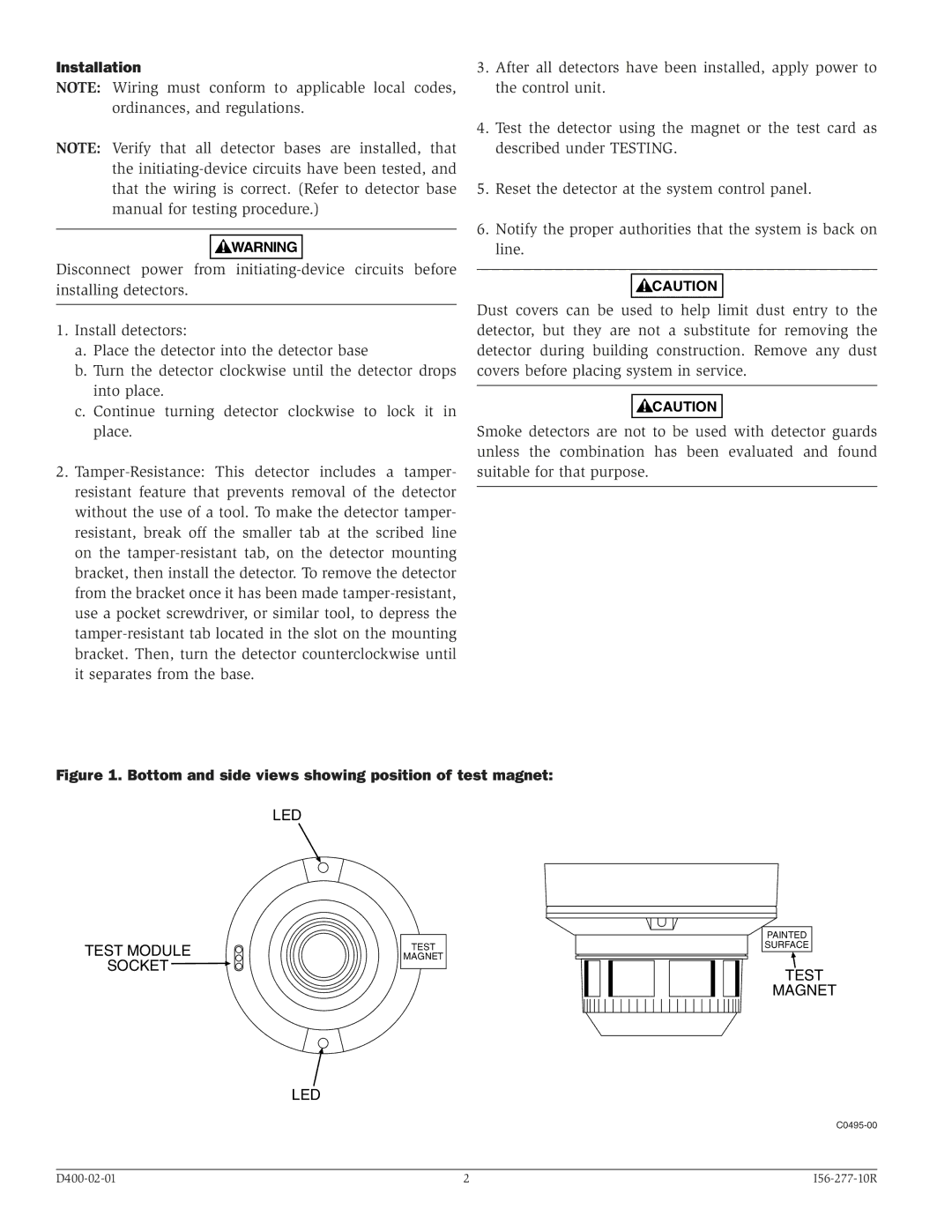
The System Sensor 2451TH and 2451 model series represent a significant advancement in the realm of smoke detection technology. Designed with an emphasis on both reliability and performance, these devices are a staple in the monitoring of environment safety in commercial and industrial settings.One of the main features of the 2451TH model is its dual sensitivity smoke detection capability. The device utilizes both photoelectric and ionization sensing technologies, allowing it to accurately detect a wide range of smoke particles from both fast-flaming and smoldering fires. This dual approach enhances its ability to respond quickly and effectively in diverse fire scenarios, ensuring optimal safety.
In addition to smoke detection, the 2451TH is equipped with a built-in heat sensor that significantly increases its performance when dealing with fire-related incidents. This feature allows the system to not only detect smoke but also rising temperatures in its environment, ensuring rapid alerting before potential threats escalate.
Both the 2451 and 2451TH models are designed to incorporate advanced communication capabilities. They can seamlessly integrate into alarm systems, providing alerts and status updates directly to central monitoring stations. This technology ensures that response teams can act swiftly and as required.
The 2451 series also stands out due to its user-centric design. Installation and maintenance are simplified through features like a removable cover for easy access, as well as a range of compatibility with different mounting options. The devices are also equipped with intelligent software that helps reduce false alarms while maintaining reliability, making them ideal for locations where nuisance alarms could lead to operational difficulties.
Furthermore, the 2451 and 2451TH models are compliant with numerous safety regulations, which bolsters their credibility. They are suitable for a variety of applications, ranging from educational facilities, healthcare institutions, to large corporate offices.
In summary, the System Sensor 2451TH and 2451 smoke detectors are defined by their advanced smoke and heat detection capabilities, user-friendly installation features, and robust communication technologies. These characteristics make them essential tools for fire safety, safeguarding people and property through their innovative design and reliable performance. The continuous improvements and updates to the technology ensure that they remain at the forefront of fire detection solutions.