Manuals
/
System Sensor
/
Household Appliance
/
Smoke Alarm
System Sensor
DH100LP Install the sampling tube as follows, Modifications of Sampling Tubes
Models:
DH100LP
1
4
8
8
Download
8 pages
20.5 Kb
1
2
3
4
5
6
7
8
Page 4
Image 4
Page 3
Page 5
Page 4
Image 4
Page 3
Page 5
Contents
Before Installing
Table of Contents
2 Limitations Of Duct Smoke Detectors
1 General Description
5Installation Sequence
4Contents Of The Duct Smoke Detector Kit
5.2 Drill The Mounting Holes
5.3 Secure The Detector Housing To The Duct
CAUTION Do not overtighten the screws
duct widths
Outside Duct Width
Install the sampling tube as follows
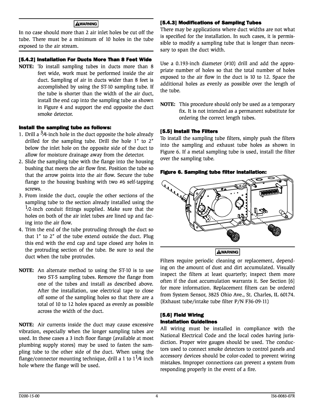
5.5 Install The Filters
Figure 6. Sampling tube filter installation
5.6 Field Wiring Installation Guidelines
Wiring Instructions
5.8 Install The Cover
6.1.2 Air Flow Test using Aerosol Smoke
5.7 Perform Detector Check
6.1.5 Filter Replacement
Figure 7. Procedure for verifying air flow
D200-15-00
6.2.2 Alarm Tests 6.2.2.1 M02-04-00Magnet Test
Figure 10. Testing detector alarm
7 Detector Cleaning Procedures
8.0 Board Replacement
Electrical Ratings - includes base and detector
Top
Page
Image
Contents