Installation
Tools and supplies needed
You will need two pieces of 2x stock to match your existing framing, a saw to cut the hole in the ceiling, a hammer or screw gun to attach the blocking to the existing joists and both a flat head and Phillips head screw driver to attach the grille and for the electrical work.
Figure 1
Figure 2
Figure 3
Figure 4
Figure 5
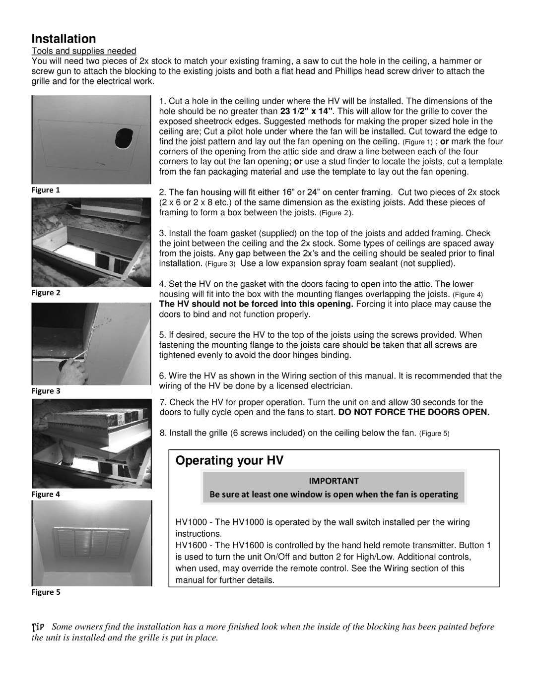
1.Cut a hole in the ceiling under where the HV will be installed. The dimensions of the hole should be no greater than 23 1/2" x 14". This will allow for the grille to cover the exposed sheetrock edges. Suggested methods for making the proper sized hole in the ceiling are; Cut a pilot hole under where the fan will be installed. Cut toward the edge to find the joist pattern and lay out the fan opening on the ceiling. (Figure 1) ; or mark the four corners of the opening from the attic side and draw a line between each of the four corners to lay out the fan opening; or use a stud finder to locate the joists, cut a template from the fan packaging material and use the template to lay out the fan opening.
2.The fan housing will fit either 16” or 24” on center framing. Cut two pieces of 2x stock (2 x 6 or 2 x 8 etc.) of the same dimension as the existing joists. Add these pieces of framing to form a box between the joists. (Figure 2).
3.Install the foam gasket (supplied) on the top of the joists and added framing. Check the joint between the ceiling and the 2x stock. Some types of ceilings are spaced away from the joists. Any gap between the 2x’s and the ceiling should be sealed prior to final installation. (Figure 3) Use a low expansion spray foam sealant (not supplied).
4.Set the HV on the gasket with the doors facing to open into the attic. The lower
housing will fit into the box with the mounting flanges overlapping the joists. (Figure 4) The HV should not be forced into this opening. Forcing it into place may cause the doors to bind and not function properly.
5.If desired, secure the HV to the top of the joists using the screws provided. When fastening the mounting flange to the joists care should be taken that all screws are tightened evenly to avoid the door hinges binding.
6.Wire the HV as shown in the Wiring section of this manual. It is recommended that the wiring of the HV be done by a licensed electrician.
7.Check the HV for proper operation. Turn the unit on and allow 30 seconds for the doors to fully cycle open and the fans to start. DO NOT FORCE THE DOORS OPEN.
8.Install the grille (6 screws included) on the ceiling below the fan. (Figure 5)
Operating your HV
IMPORTANT
Be sure at least one window is open when the fan is operating
HV1000 - The HV1000 is operated by the wall switch installed per the wiring instructions.
HV1600 - The HV1600 is controlled by the hand held remote transmitter. Button 1 is used to turn the unit On/Off and button 2 for High/Low. Additional controls, when used, may override the remote control. See the Wiring section of this manual for further details.
![]()
![]() Some owners find the installation has a more finished look when the inside of the blocking has been painted before the unit is installed and the grille is put in place.
Some owners find the installation has a more finished look when the inside of the blocking has been painted before the unit is installed and the grille is put in place.
