An A/V 80Hz high pass filter switch provides instant conversion to 5.1 and higher order systems where a separate subwoofer below 80Hz is required. Filter characteristics are according to the international standards for this setup. This response is also shown diagramatically in Figure 1.
Listening to well recorded male or female spoken word or vocals at the normal listening position is a good way to check and optimise the available settings. Difficult environments and variable listening distances produce varying degrees of boost from the flat position in the 50Hz to 800Hz area. Graphical representations of the responses available by setting the switches are shown below. The linear or flat response positions for the DIP switches are always clearly shown in the diagrams below and also on the rear panel of the speaker.
The Tannoy ActivAssist™ software package is available to help with the DIP switch settings. Using a standard laptop with the microphone and cables supplied in the pack, the performance of the speaker in a particular environment can be assessed and a recommended set of switches set up.
| | | | +1.5dB | +3dB |
| +1.5dB | Large | Medium Normal | +2dB |
| +0.75dB |
0dB | Flat | Flat | | +1dB |
| Flat | Flat |
| -1dB | -2dB | | -0.75dB | -1dB |
| -4dB | | -1.5dB | -2dB |
| | -6dB | | -3dB |
| -2dB | | |
-8dB
-3dB
( AV 80Hz HiPass on slide switch)
Fig. 1. Full range of equalisation and trim available.
3.1: ANALOG INPUT
XLR: | 2= +ve (hot), 3= -ve (cold), 1= screen, shield or signal ground. |
3 way Jack: | tip=+ve (hot), ring= -ve (cold), sleeve= screen, shield or signal ground. |
For unbalanced | XLR connection short pin 1 to pin 3 and use 2= +ve (hot), 3= -ve (ground). |
For unbalanced | 3 way Jack short ring to sleeve and use tip= +ve (hot), sleeve= -ve (ground). |
3.2: DIGITAL SPDIF INPUT
The input impedance is the SPDIF specification at 75 ohms and the 24 bit DAC supports 44.1, 48 and 96kHz sampling rates. Please use a high quality* SPDIF coaxial phono (RCA) cable to connect the source equipment (eg CD player, DAT/ADAT or PC sound card) to one of the speakers. Connect a second (phono to phono) high quality cable from this speaker to the second speaker of the stereo pair. Select whether each speaker converts left channel or right channel audio as appropriate using the switch adjacent to the SPDIF input connector. For true mono requirements set the switch to mono. If volume can be controlled from the source equipment, set the source equipment volume level to minimum and the speaker volume control to maximum (fully clockwise). If volume cannot be controlled by the source equipment (eg a simple CD or DAT etc) set the volume control on the speaker to minimum (fully anticlockwise) to prevent excessive sound levels. The volume control adjusts the analogue level after the DA converters to preserve the full digital dynamic range.
*In order to comply fully with EMC regulations, the SPDIF input and SPDIF thru should be connected using metal-shelled connectors and good quality shielded cable suitable for digital audio.
3.3: CONNECTING YOUR SPEAKERS
Having chosen an appropriate location for your monitors and arranged them accordingly, connect the power cord to the mains socket and turn the power on. The LED on the front panel will now glow red. Push the Tannoy logo on the front panel to operate the switch to bring the amplifier out of standby mode and into operational mode. Set the volume control on the rear panel to zero (fully anticlockwise). Connect the audio signal source (console output) to the input connector (combined XLR/jack socket) or SPDIF at the back of the monitor.
3.4: USER CONTROLS
A/V (80Hz): a switch to the bottom left of the bank of DIP switches sets the system high pass filter to either flat or –6dB at 80Hz. The 80Hz setting is used when the speakers are in combination with a subwoofer for low frequency effects such as Dolby Digital, AC3, DTS etc playback situations. For all other situations set this switch to flat. This response can be seen in Figure 1 above.
Left/Right/Mono: a switch at the bottom left of the bank of DIP switches sets the SPDIF DAC to sense the left, right or combined stereo information (mono) from the digital stream. Set the left hand speaker to ‘Left’ and the right hand speaker to ‘Right’ for 2 channel stereo, or to ‘mono’ for single speaker monitoring.
Analogue/Digital: a switch adjacent to the XLR/Jack combi socket selects whether the speaker is receiving a signal from the balanced/unbalanced analogue input combi socket, or, from the SPDIF phono (RCA) digital input. Both may be connected simultaneously but only one can be selected at any one time.
4.0: EQUALISATION POSSIBILITIES
Note: In the diagrams which follow, the corner frequency shown as 50Hz will vary according to the specification relating to the particular model which has been chosen. Please refer to the detailed specification section at the end of this manual for more details. Smaller models will have a slightly higher corner frequency and larger models will have a lower corner frequency. The diagrams have been prepared to make the visualisation of the EQ possibilities easier to understand. The transitions of the speaker amplitude response bewteen frequency bands will be gradual and not as sharp as the diagrams show. Note the +10dB and -10dB calibrations on the charts. EQ settings should never be at opposite extremes eg -8dB low mid contour with -2dB mids and +3dB highs.
There are 4 basic frequency bands that can be adjusted. The range of adjustment is purposely restricted so that although effective in the majority of environments, it is difficult to set the speaker to have a totally unacceptable response. A 'flat' setting means flat within specification as measured in an anechoic chamber, on axis, under free field conditions in the far field (3 metres away). The frequency bands are:
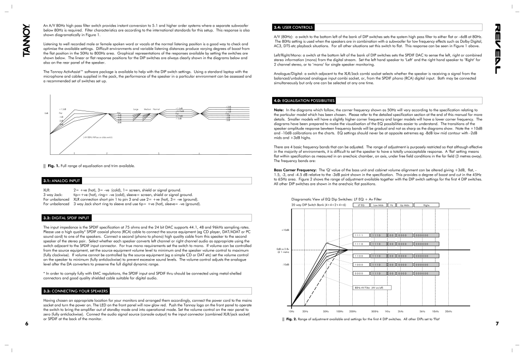
Bass Corner Frequency: The 'Q' value of the bass unit and cabinet volume alignment can be altered giving +3dB, flat, - 1.5, -3, and -4.5 dB relative to the -3dB point shown in the specification. This provides a degree of boost and cut in the 45Hz to 65Hz area. Figure 2 shows the range of adjustment available together with the DIP switch settings for the first 4 DIP switches. All other DIP switches are shown in the anechoic flat positions.
Diagramatic View of EQ Dip Switches: LF EQ + Av Filter
20 way DIP Switch Bank (4+4+2+4+6) | LF EQ | | Low Mids | | Hz | | Up Mids | | Highs |
+10dB | | | | | | | | | | | |
| | | | | | | |
| | 1 1 1 1 | | 1 1 1 0 | | 0 0 | | 0 0 0 0 | | 0 0 0 0 0 0 | |
| | | | | | | | | | | |
| | 1 1 1 0 | | 1 1 1 0 | | 0 0 | | 0 0 0 0 | | 0 0 0 0 0 0 | |
0dB re 2.8v | | | | | | | | | | | |
@ 1 metre | | | | | | | | | | | |
| | 1 1 0 0 | | 1 1 1 0 | | 0 0 | | 0 0 0 0 | | 0 0 0 0 0 0 | |
-10dB | | | | | | |
| 1 0 0 0 | | 1 1 1 0 | | 0 0 | | 0 0 0 0 | | 0 0 0 0 0 0 | |
| | | | | | | | | | | |
| | 0 0 0 0 | | 1 1 1 0 | | 0 0 | | 0 0 0 0 | | 0 0 0 0 0 0 | |
80Hz AV Filter (AV on/off)
10Hz | 20Hz | 50Hz | 100Hz | 200Hz | 500Hz | 1Khz | 2kHz | 5kHz | 10kHz | 20kHz |
Fig. 2. Range of adjustment available and settings for the first 4 DIP switches. All other DIPs set to 'Flat'