Cable choice consists mainly of selecting the correct cross sectional area in relation to the cable length and the load impedance. A small cross sectional area would increase the cables series resistance, inducing power loss and response variations (damping factor).
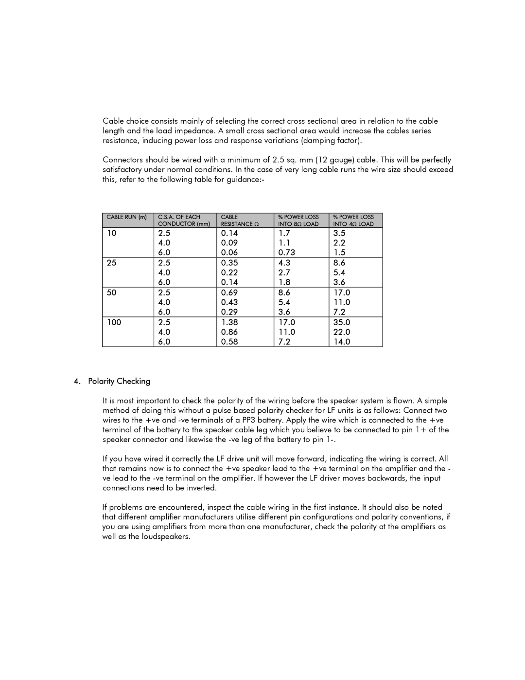
Connectors should be wired with a minimum of 2.5 sq. mm (12 gauge) cable. This will be perfectly satisfactory under normal conditions. In the case of very long cable runs the wire size should exceed this, refer to the following table for guidance:-
CABLE RUN (m) | C.S.A. OF EACH | CABLE | % POWER LOSS | % POWER LOSS |
| CONDUCTOR (mm) | RESISTANCE Ω | INTO 8Ω LOAD | INTO 4Ω LOAD |
10 | 2.5 | 0.14 | 1.7 | 3.5 |
| 4.0 | 0.09 | 1.1 | 2.2 |
| 6.0 | 0.06 | 0.73 | 1.5 |
25 | 2.5 | 0.35 | 4.3 | 8.6 |
| 4.0 | 0.22 | 2.7 | 5.4 |
| 6.0 | 0.14 | 1.8 | 3.6 |
50 | 2.5 | 0.69 | 8.6 | 17.0 |
| 4.0 | 0.43 | 5.4 | 11.0 |
| 6.0 | 0.29 | 3.6 | 7.2 |
100 | 2.5 | 1.38 | 17.0 | 35.0 |
| 4.0 | 0.86 | 11.0 | 22.0 |
| 6.0 | 0.58 | 7.2 | 14.0 |
4. Polarity Checking
It is most important to check the polarity of the wiring before the speaker system is flown. A simple method of doing this without a pulse based polarity checker for LF units is as follows: Connect two wires to the +ve and
If you have wired it correctly the LF drive unit will move forward, indicating the wiring is correct. All that remains now is to connect the +ve speaker lead to the +ve terminal on the amplifier and the - ve lead to the
If problems are encountered, inspect the cable wiring in the first instance. It should also be noted that different amplifier manufacturers utilise different pin configurations and polarity conventions, if you are using amplifiers from more than one manufacturer, check the polarity at the amplifiers as well as the loudspeakers.
