SQ•2 Features
|
|
|
|
| 3 |
| 4 |
| CHANNEL 1 | 6 |
|
| 8 | 10 |
|
|
| 11 |
|
|
|
|
|
|
|
|
|
|
|
|
|
|
|
| 12 | |
1 |
| GATE |
|
|
| 5 |
|
| GAIN REDUCTION(dB) | GATE |
|
|
|
|
| CHANNEL 2 |
|
|
|
|
| AIR | ||||||||||||||
|
|
|
| COMPRESSOR / LIMITER |
|
|
|
| AIR |
|
|
| COMPRESSOR / LIMITER |
|
|
|
| |||||||||||||||||||
- | 2 | 2.5 | 10 | 50 | 0.5 | 1 | 0 |
|
| 30 | 20 | 15 | 10 6 | 4 | 2 | 1 | 2 | 2.5 | 10 | 50 | 0.5 | 1 | 0 |
|
| |||||||||||
50 | 0 | 5 | 100 | 0.3 | +6 |
|
| CH 1 |
|
|
|
|
|
| 0 | 5 | 100 | 0.3 | +6 |
| ON | |||||||||||||||
|
|
|
| +10 |
|
|
|
|
|
|
|
|
|
|
|
|
|
|
|
|
|
| +10 |
|
|
|
|
|
|
|
| |||||
|
| 0 |
| 8 1 | 150 | 0.1 |
| 2 | +14 |
|
|
|
|
|
|
|
|
| 0 |
| 8 1 | 150 | 0.1 |
| 2 | +14 |
|
| ||||||||
|
|
| 1.5 |
|
|
|
| CH 2 |
|
|
|
|
|
|
| 1.5 |
|
|
|
| ||||||||||||||||
|
|
|
|
|
|
|
|
|
|
|
|
|
|
| CH 1 |
|
|
| CH 2 |
|
|
|
|
|
|
|
|
|
|
|
|
|
| |||
| OFF | +10 | +20 | 1 | LIM | 0.1 | 200 | 50ms | 3 | +20 | OFF | FULL | AUTO | IN |
| AUTO | IN | OFF | +10 | +20 | 1 | LIM | 0.1 | 200 | 50ms | 3 | +20 | OFF | FULL | |||||||
|
|
|
| |||||||||||||||||||||||||||||||||
|
| dBu |
|
| dBu |
| n:1 |
| ms | sec |
|
| dB |
|
|
|
|
|
|
|
|
| dBu |
|
| dBu |
| n:1 |
| ms | sec |
|
| dB |
|
|
|
|
| CLOSE |
|
|
|
| AUTO |
|
| CHAN 1 |
|
|
|
|
|
|
|
|
| CLOSE |
|
|
|
| AUTO |
|
| CHAN 2 | POWER | ||||||
|
|
|
|
|
|
|
|
| IN/OUT |
|
| IN/OUT |
|
|
|
|
|
|
|
|
|
|
|
|
|
|
|
| IN/OUT |
|
| IN/OUT |
| |||
| THRESHOLD | THRESHOLD |
| RATIO | ATTACK | RELEASE |
| OUTPUT |
| LEVEL |
|
|
|
|
|
|
| THRESHOLD | THRESHOLD |
| RATIO | ATTACK | RELEASE |
| OUTPUT |
| LEVEL | |||||||||
|
|
| 2 |
|
|
|
| 7 |
|
| 9 |
|
|
|
|
|
|
|
|
|
|
|
|
|
|
|
|
|
|
|
|
|
|
| ||
|
|
|
|
|
|
|
|
|
|
|
|
|
|
|
|
|
|
|
|
|
|
|
|
|
|
|
|
|
|
|
|
|
| |||
BY ![]()
![]()
![]()
SQ•2
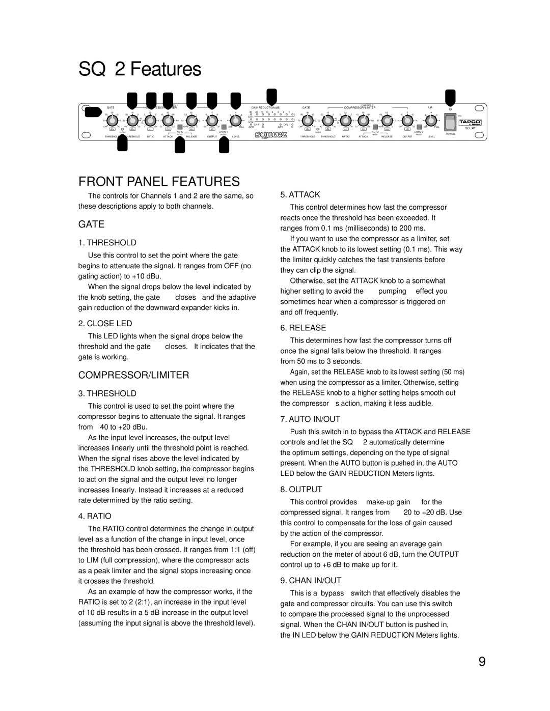
FRONT PANEL FEATURES
The controls for Channels 1 and 2 are the same, so these descriptions apply to both channels.
GATE
1. THRESHOLD
Use this control to set the point where the gate begins to attenuate the signal. It ranges from OFF (no gating action) to +10 dBu.
When the signal drops below the level indicated by the knob setting, the gate “closes” and the adaptive gain reduction of the downward expander kicks in.
5. ATTACK
This control determines how fast the compressor reacts once the threshold has been exceeded. It ranges from 0.1 ms (milliseconds) to 200 ms.
If you want to use the compressor as a limiter, set the ATTACK knob to its lowest setting (0.1 ms). This way the limiter quickly catches the fast transients before they can clip the signal.
Otherwise, set the ATTACK knob to a somewhat higher setting to avoid the “pumping” effect you sometimes hear when a compressor is triggered on and off frequently.
2. CLOSE LED
This LED lights when the signal drops below the threshold and the gate “closes.” It indicates that the gate is working.
COMPRESSOR/LIMITER
3. THRESHOLD
This control is used to set the point where the compressor begins to attenuate the signal. It ranges from
As the input level increases, the output level increases linearly until the threshold point is reached. When the signal rises above the level indicated by the THRESHOLD knob setting, the compressor begins to act on the signal and the output level no longer increases linearly. Instead it increases at a reduced rate determined by the ratio setting.
4. RATIO
The RATIO control determines the change in output level as a function of the change in input level, once the threshold has been crossed. It ranges from 1:1 (off) to LIM (full compression), where the compressor acts as a peak limiter and the signal stops increasing once it crosses the threshold.
As an example of how the compressor works, if the RATIO is set to 2 (2:1), an increase in the input level of 10 dB results in a 5 dB increase in the output level (assuming the input signal is above the threshold level).
6. RELEASE
This determines how fast the compressor turns off once the signal falls below the threshold. It ranges from 50 ms to 3 seconds.
Again, set the RELEASE knob to its lowest setting (50 ms) when using the compressor as a limiter. Otherwise, setting the RELEASE knob to a higher setting helps smooth out the compressor’s action, making it less audible.
7. AUTO IN/OUT
Push this switch in to bypass the ATTACK and RELEASE controls and let the SQ•2 automatically determine the optimum settings, depending on the type of signal present. When the AUTO button is pushed in, the AUTO LED below the GAIN REDUCTION Meters lights.
8. OUTPUT
This control provides
For example, if you are seeing an average gain reduction on the meter of about 6 dB, turn the OUTPUT control up to +6 dB to make up for it.
9. CHAN IN/OUT
This is a “bypass” switch that effectively disables the gate and compressor circuits. You can use this switch to compare the processed signal to the unprocessed signal. When the CHAN IN/OUT button is pushed in, the IN LED below the GAIN REDUCTION Meters lights.
9