1 – Starting to use the RC-828
The TASCAM RC-828 Remote Control Unit allows you to control up to 4 DTRS1 recorders (any combination of DA-98, DA-38 or DA-98 units) from one location. The functions which may be controlled are:
•Transport operations (including jog and shuttle)
•Track arming
•Auto punch operations
•Chasing control
•Location memories and auto-repeat between two points
This manual makes reference to the manuals of the following units: DA-88, DA-38, DA-98 and SY-88. Please consult these documents as neces- sary when setting up and using the RC-828.
1.1 Hooking up the RC-828
The RC-828 and DTRS units form a “daisy- chain”, with the RC-828 being at the head, and the “tail” unit being terminated with the terminator supplied with the RC-828.
NOTE
When you connect a number of DTRS units which are of different types, including a DA-98, the DA-98 should be at the head of the chain immediately following the RC-828. Other units may then be connected in any order.
If the DTRS units are DA-88s and DA-38s only, they may be connected in any order.
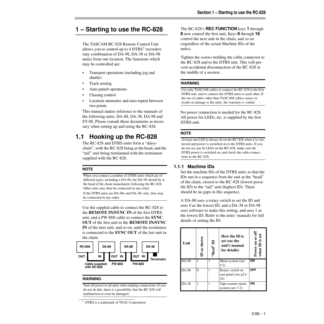
Use the suppled cable to connect the RC-828 to the REMOTE IN/SYNC IN of the first DTRS unit, and a PW-88S cable to connect the SYNC OUT of the first unit to the REMOTE IN/SYNC IN of the next unit, and so on, until the terminator is connected to the SYNC OUT of the last unit in the chain.
OUT | IN | OUT IN | OUT | IN |
| | | | Terminator |
| Cable supplied | PW-88S | PW-88S |
| with RC-828 | | | |
WARNING
Turn off power to all units when making connections. If you do not do this, there is a possibility that the RC-828 will malfunction or even be damaged.
1DTRS is a trademark of TEAC Corporation
The RC-828’s REC FUNCTION keys 1 through 8 now control the first unit, Keys 9 through 16 control the next unit in the chain, and so on (regardless of the actual Machine IDs of the units).
Tighten the screws holding the cable connector to the RC-828 and to the DTRS unit. This will pre- vent accidental disconnection of the RC-828 in the middle of a session.
WARNING
Use only TASCAM cables to connect the RC-828 to the first DTRS unit, and to connect the DTRS units to each other. If the use of cables other than TASCAM cables causes or results in damage to the units, the warranty is voided.
No power connection is needed for the RC-828. All power for LEDs, etc. is supplied by the first DTRS unit.
NOTE
At least one LED is always lit on the RC-828 when it is con- nected and power is switched on to the DTRS units. If you do not see any lit LEDs on the RC-828, make sure the DTRS power is switched on, and check the cable connec- tions to the RC-828.
1.1.1 Machine IDs
Set the machine IDs of the DTRS units so that the IDs run in a sequence from the unit at the “head” of the chain, closest to the RC-828 (lowest possi- ble ID) to the “tail” unit (highest ID). There should be no gaps in this sequence.
A DA-88 uses a rotary switch to set the ID and uses 0 as the lowest ID, and a DA-38 or DA-98 uses software to make this setting, and uses 1 as the lowest ID. Refer to the units’ manuals for full details of setting the ID.
| | ID as shown | | How the ID is | Power on or off when ID is set |
| Unit | “Real” ID | set (see the |
| unit’s manual |
| |
| | for details) |
| | |
| | | | | |
| DA-98 | 1 | 1 | Menu system (see | ON |
| | | | 9.2) | |
| | | | | |
| DA-88 | 0 | 1 | Rotary switch on | OFF |
| | | | rear panel (see p23– | |
| | | | 24) | |
| | | | | |
| DA-38 | 1 | 1 | Tape counter menu | ON |
| | | | system (see 7-2) | |
| | | | | |