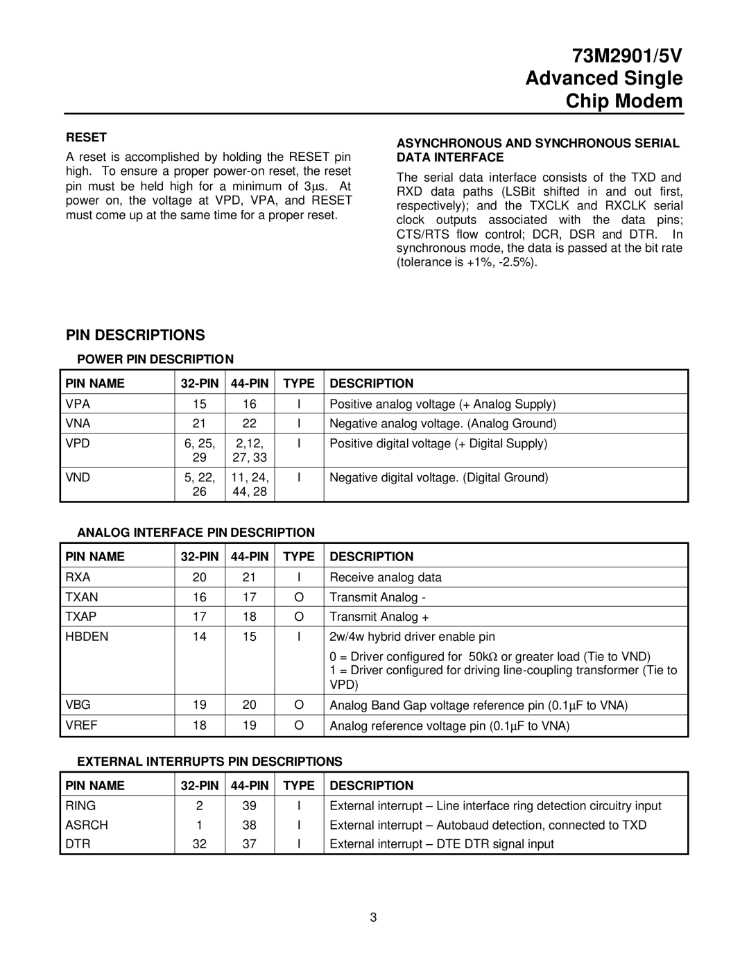
73M2901/5V specifications
The TDK 73M2901/5V is a compact and versatile power management IC designed for a wide array of applications, particularly in portable electronic devices. This chip is part of TDK's extensive lineup of power management solutions, showcasing advanced technologies and features that cater to the evolving needs of modern electronics.One of the standout characteristics of the TDK 73M2901/5V is its ability to support a broad input voltage range. This flexibility allows the device to operate efficiently with various power supply configurations, making it suitable for battery-operated devices, USB-powered systems, and more. Its robust design ensures that it can maintain stable performance even under fluctuating voltage conditions, a critical attribute for portable applications.
The 73M2901/5V integrates several key power management features, including voltage regulation, power distribution, and battery management functionalities. The integrated voltage regulator provides precise output voltage control, helping to preserve battery life by managing power consumption effectively. This feature is particularly essential for devices that rely on rechargeable batteries, as it enhances overall efficiency and prolongs usage times between charges.
In addition to voltage regulation, the TDK 73M2901/5V boasts advanced power distribution capabilities. The chip can intelligently manage power routing among multiple components within a device, ensuring optimal performance without unnecessary power loss. This is crucial for devices that incorporate various subsystems, needing coordinated power management to function seamlessly.
Furthermore, the 73M2901/5V includes built-in battery management capabilities that facilitate safe charging and discharging processes. This feature not only guards against overcharging and overheating but also extends the lifespan of lithium-ion and lithium-polymer batteries commonly found in consumer devices.
From a technological standpoint, the TDK 73M2901/5V utilizes cutting-edge semiconductor processes that enhance its efficiency and thermal performance. This results in reduced heat generation, allowing for compact designs without the risk of overheating. The chip is also designed for low quiescent current, which minimizes power draw during standby or idle states, further enhancing energy efficiency.
Overall, the TDK 73M2901/5V is a highly capable power management IC that combines robustness, efficiency, and advanced features. Its adaptability to various power configurations, integrated management capabilities, and modern semiconductor technologies make it an ideal choice for developers seeking reliable solutions for their portable electronic designs. As technology continues to advance, solutions like the TDK 73M2901/5V will play an increasingly vital role in powering the next generation of electronic devices.