Advance Data Sheet: FReta iEB Series –Single Output Eighth Brick Bus Converter

Thermal Management:

An important part of the overall system design process is thermal management; thermal design must be considered at all levels to ensure good reliability and lifetime of the final system. Superior thermal design

to the airflow direction can have a significant impact on the module’s thermal performance.

Thermal Derating: For proper application of the power module in a given thermal environment, output current derating curves are provided as a design

and the ability to operate in severe application environments are key elements of a robust, reliable power module.

A finite amount of heat must be dissipated from the power module to the surrounding environment. This heat is transferred by the three modes of heat transfer: convection, conduction and radiation. While all three modes of heat transfer are present in every application, convection is the dominant mode of heat transfer in most applications. However, to ensure adequate cooling and proper operation, all three modes should be considered in a final system configuration.

The open frame design of the power module provides an air path to individual components. This air path improves convection cooling to the surrounding

Module

Centerline

76 (3.0)

AIRFLOW

Adjacent PCB

A12.7

I

(0.50)

R


F


L


O


W


environment, which reduces areas of heat concentration and resulting hot spots.

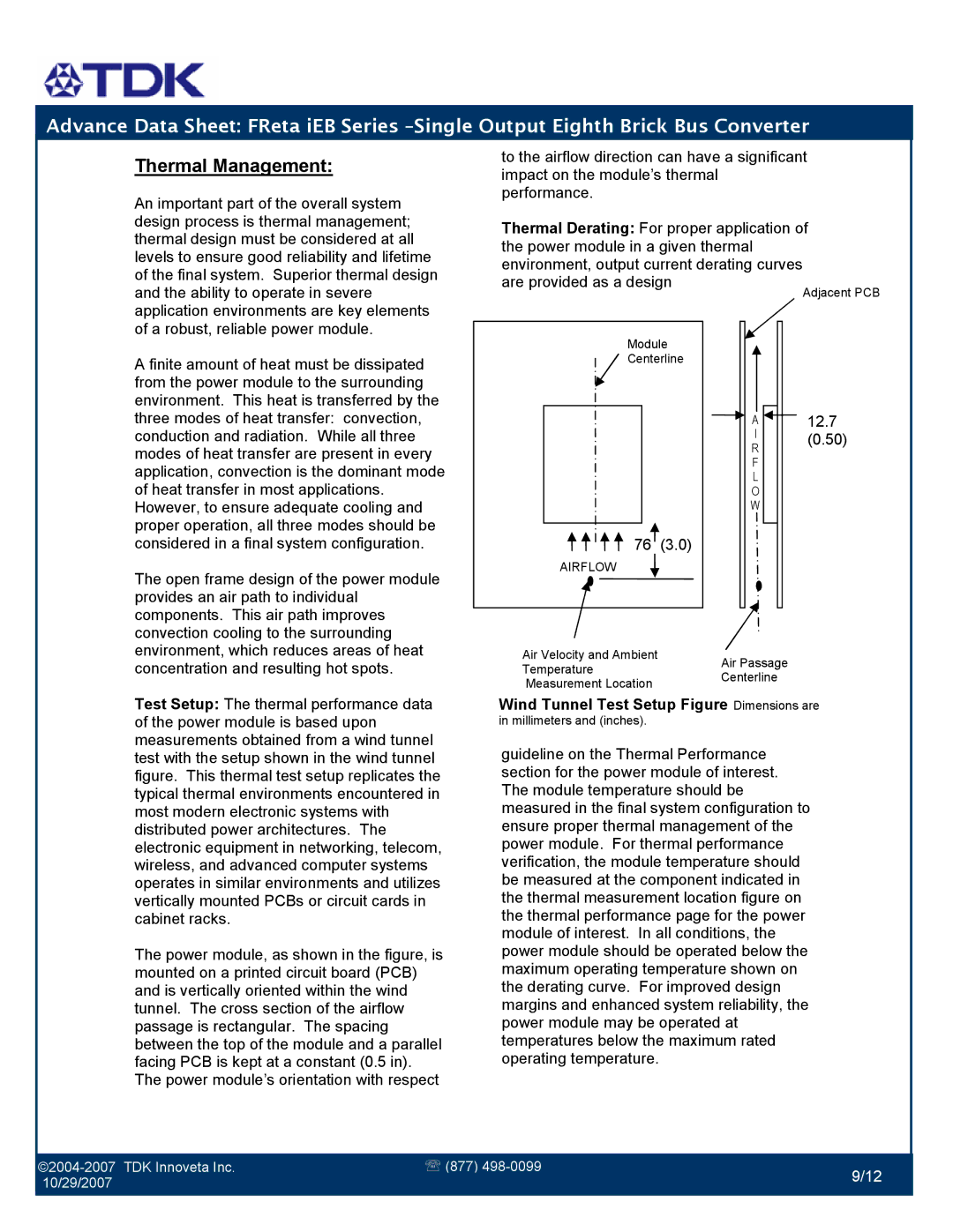
Test Setup: The thermal performance data of the power module is based upon measurements obtained from a wind tunnel test with the setup shown in the wind tunnel figure. This thermal test setup replicates the typical thermal environments encountered in most modern electronic systems with distributed power architectures. The electronic equipment in networking, telecom, wireless, and advanced computer systems operates in similar environments and utilizes vertically mounted PCBs or circuit cards in cabinet racks.

The power module, as shown in the figure, is mounted on a printed circuit board (PCB) and is vertically oriented within the wind tunnel. The cross section of the airflow passage is rectangular. The spacing between the top of the module and a parallel facing PCB is kept at a constant (0.5 in). The power module’s orientation with respect

Air Velocity and Ambient

Air Passage

Temperature

Centerline

Measurement Location


Wind Tunnel Test Setup Figure Dimensions are in millimeters and (inches).

guideline on the Thermal Performance section for the power module of interest. The module temperature should be measured in the final system configuration to ensure proper thermal management of the power module. For thermal performance verification, the module temperature should be measured at the component indicated in the thermal measurement location figure on the thermal performance page for the power module of interest. In all conditions, the power module should be operated below the maximum operating temperature shown on the derating curve. For improved design margins and enhanced system reliability, the power module may be operated at temperatures below the maximum rated operating temperature.

©2004-2007 TDK Innoveta Inc.

￿ (877) 498-0099

10/29/2007

9/12


Page 9
Image 9
TDK iEB Series manual Thermal Management

iEB Series specifications

The TDK iEB Series represents a significant advancement in the realm of energy-efficient power supplies, designed to cater to various applications requiring highly dependable performance. TDK, a global leader in electronic components and solutions, has integrated innovative technologies into the iEB Series to enhance efficiency, reliability, and versatility.

One of the standout features of the iEB Series is its exceptional efficiency rating, which often exceeds 90%. This high level of efficiency is crucial for modern electronic devices, as it not only reduces energy consumption but also minimizes heat production, prolonging the lifespan of components and lowering cooling requirements. The iEB Series is built with state-of-the-art materials and advanced circuit designs, which contribute to its efficiency by reducing energy losses during the power conversion process.

The iEB Series is equipped with a wide input voltage range, making it suitable for various applications across different sectors, including industrial, telecommunications, and renewable energy. The flexibility of input voltage ensures that these power supplies can operate effectively in diverse environments and configurations, delivering robust performance in demanding conditions.

Another key characteristic of the iEB Series is its compact design. TDK has prioritized space-saving solutions, allowing these power supplies to fit into tighter spaces without sacrificing performance. This is particularly advantageous for applications where board real estate is limited, and efficient design is paramount.

The series also features built-in protection mechanisms, including overvoltage, overcurrent, and thermal protection. These safety features ensure that the power supplies operate reliably and mitigate risks associated with electrical anomalies, ensuring a longer operational life for both the power supply and connected devices.

Moreover, the iEB Series adopts advanced digital control technologies, enabling precise regulation of output voltages and currents. This capability allows for better system integration and adaptability in dynamically changing electrical environments, making the iEB Series ideal for modern smart devices and IoT applications.

In summary, the TDK iEB Series presents a perfect combination of efficiency, versatility, and reliability. With its high efficiency, broad input range, compact design, and comprehensive protection features, it stands as a leading choice for engineers and designers looking for a dependable power supply solution in their projects. The commitment of TDK to innovation ensures that the iEB Series remains at the forefront of power supply technology.