GB
Installation
To fix the extractor to the kitchen unit the pattern on page 18 is used.
The lower part of the extractor must be located at a minimum height of 60 cm above the hob for electric cookers and 65 cm for gas cookers. If the instructions of a gas cooker indicate a greater distance these must be observed.
The extractor must be connected to a wall socket with an effective earth. When the extractor is working at the same time as other
To achieve optimum performance the length of the outlet hose should not exceed 4 meters, or include more than two 90º angles (elbows).
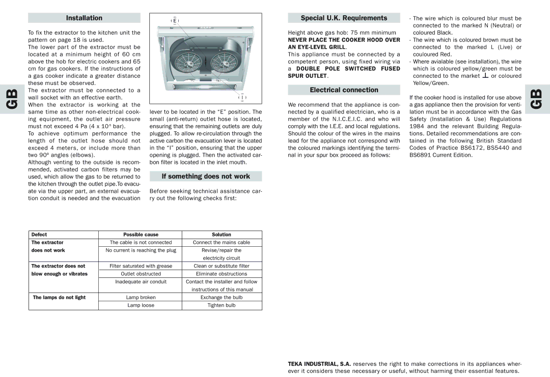
Although venting to the outside is recom- mended, activated carbon filters may be used, which allow the gas to be returned to the kitchen through the outlet pipe.To evacu- ate via the upper part, an external evacua- tion conduit is needed and the evacuation
E |
I |
lever to be located in the “E” position. The small
If something does not work
Before seeking technical assistance car- ry out the following checks first:
Special U.K. Requirements
Height above gas hob: 75 mm minimum
NEVER PLACE THE COOKER HOOD OVER AN EYE-LEVEL GRILL.
This appliance must be connected by a competent person, using fixed wiring via a DOUBLE POLE SWITCHED FUSED
SPUR OUTLET.
Electrical connection
We recommend that the appliance is con- nected by a qualified electrician, who is a member of the N.I.C.E.I.C. and who will comply with the I.E.E. and local regulations. Should the colour of the wires in the mains lead for the appliance not correspond with the coloured markings identifying the termi- nal in your spur box proceed as follows:
-The wire which is coloured blur must be connected to the marked N (Neutral) or coloured Black.
-The wire which is coloured brown must be connected to the marked L (Live) or couloured Red.
-Where avialable (see installation), the wire
which is coloured yellow/green must be
connected to the market or coloured Yellow/Green.
If the cooker hood is installed for use above a gas appliance then the provision for venti- lation must be in accordance with the Gas Safety (Installation & Use) Regulations 1984 and the relevant Building Regula- tions. Detailed recommendations are con- tained in the following British Standard Codes of Practice BS6172, BS5440 and BS6891 Current Edition.
GB
Defect | Possible cause | Solution |
|
|
|
The extractor | The cable is not connected | Connect the mains cable |
does not work |
|
|
No current is reaching the plug | Revise/repair the | |
|
| electricity circuit |
The extractor does not | Filter saturated with grease | Clean or substitute filter |
blow enough or vibrates | Outlet obstructed | Eliminate obstructions |
| Inadequate air conduit | Contact the installer and follow |
|
| instructions of this manual |
The lamps do not light | Lamp broken | Exchange the bulb |
| Lamp loose | Tighten bulb |
|
|
|
TEKA INDUSTRIAL, S.A. reserves the right to make corrections in its appliances wher- ever it considers these necessary or useful, without harming their essential features.
