DIAMOND LOBBY
GUESTROOM TELEPHONE USERS GUIDE
CONNECTING THE DIAMOND LOBBY
Included with the Diamond Lobby are (one each):
• | Base unit | • | Coiled handset cord | • | User guide |
• | Handset | • | Clear plastic overlay | • | Line cord |
Contact your supplier or Teledex for information on ordering custom designed and printed faceplates to enhance the look of your Teledex Diamond telephone.
1)Located on the left side of the Diamond Lobby is a modular jack labeled TO HANDSET. Insert one end of the coiled handset cord into this jack. (You should hear the coil cord lick when properly inserted).
2)Insert the other end of the coiled handset cord into the modular jack on the handset.
3)Turn the telephone so the back panel is facing you. Insert either end of the line cord into the jack on the back of the telephone this jack is labeled TO TEL.
4)Insert the other end of the line cord into a telephone wall jack.
5)To program the AUTO DIAL key(s) see below instructions.
6)Once your telephone is connected, place the paper faceplate over the keys. The plastic overlay slips into place by hooking the tabs on the overlay into the recessed slots located on both sides. The overlay is easiest to insert when; the left or right side tabs are inserted first, and the middle part of the overlay is slightly bowed to allow for insertion of the other tabs.
TO PROGRAM THE AUTO DIAL KEY(S)
Remove the plastic overlay and paper faceplate.
The telephone must be connected to a "live" telephone jack. Use the eraser end of a pencil or pen to depress the dial keys.
2)If the steps listed above do not provide a remedy for the suspect telephone, please place a tag on the individual telephone describing the defect. Next, call the Teledex Repair Department at 1 (800)
3)Kindly note: An RMA number is unique to each return shipment. Do not duplicate this number on any future shipments.
SHIPPING INSTRUCTIONS:
Please print the RMA number clearly on the outside of your shipping carton(s). Please ship to the following address:
Teledex LLC / RMA#___________
6311 San Ignacio Avenue
San Jose, CA 95119
FREIGHT CHARGES:
The Customer is responsible for shipping products for repair to Teledex. After repair, Teledex will return telephone products to the Customer freight prepaid in the same manner in which is was sent (i.e. Freight sent to Teledex UPS Blue, will be returned via 2 day ship- ping).
**Please note: When telephones are returned for repair due to misuse (i.e. liquid spills, abuse, or Customer modification - warranty label broken), the Customer will be charged the standard repair fee, regard- less of warranty status.
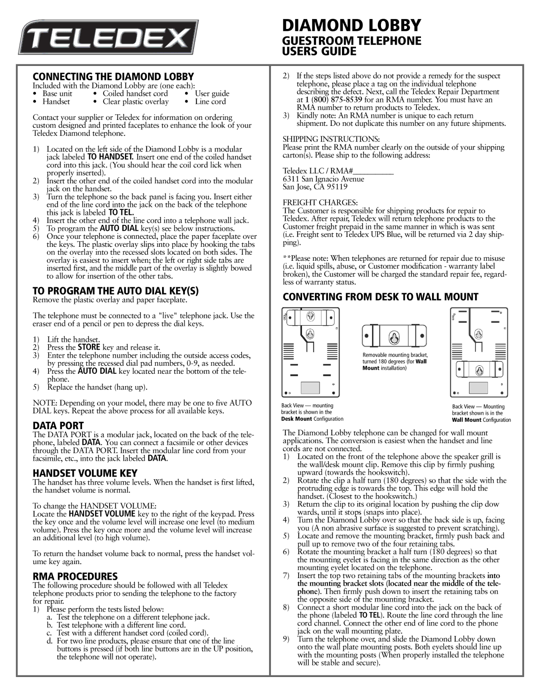
CONVERTING FROM DESK TO WALL MOUNT
1)Lift the handset.
2)Press the STORE key and release it.
3)Enter the telephone number including the outside access codes, by pressing the recessed dial pad numbers,
4)Press the AUTO DIAL key located near the bottom of the tele- phone.
5)Replace the handset (hang up).
NOTE: Depending on your model, there may be one to five AUTO DIAL keys. Repeat the above process for all available keys.
DATA PORT
Back View — mounting bracket is shown in the Desk Mount Configuration
Removable mounting bracket, turned 180 degrees (for Wall Mount installation)
Back View — Mounting bracket shown is in the Wall Mount Configuration
The DATA PORT is a modular jack, located on the back of the tele- phone, labeled DATA. You can connect a facsimile or other devices through the DATA PORT. Insert the modular line cord from your facsimile, etc., into the jack labeled DATA.
HANDSET VOLUME KEY
The handset has three volume levels. When the handset is first lifted, the handset volume is normal.
To change the HANDSET VOLUME:
Locate the HANDSET VOLUME key to the right of the keypad. Press the key once and the volume level will increase one level (to medium volume). Press the key once more and the volume level will increase an additional level (to high volume).
To return the handset volume back to normal, press the handset vol- ume key again.
RMA PROCEDURES
The following procedure should be followed with all Teledex telephone products prior to sending the telephone to the factory for repair.
1)Please perform the tests listed below:
a.Test the telephone on a different telephone jack.
b.Test telephone with a different line cord.
c.Test with a different handset cord (coiled cord).
d.For two line products, please ensure that one of the line buttons is pressed (if both line buttons are in the UP position, the telephone will not operate).
The Diamond Lobby telephone can be changed for wall mount applications. The conversion is easiest when the handset and line cords are not connected.
1)Located on the front of the telephone above the speaker grill is the wall/desk mount clip. Remove this clip by firmly pushing upward (towards the hookswitch).
2)Rotate the clip a half turn (180 degrees) so that the side with the protruding edge is towards the top. This edge will hold the handset. (Closest to the hookswitch.)
3)Return the clip to its original location by pushing the clip dow wards, until it stops (snaps into place).
4)Turn the Diamond Lobby over so that the back side is up, facing you (A non abrasive surface is suggested to prevent scratching).
5)Locate and remove the mounting bracket, firmly push back and pull up to remove two of the four retaining tabs.
6)Rotate the mounting bracket a half turn (180 degrees) so that the mounting eyelet is facing in the same direction as the other mounting eyelet located on the telephone.
7)Insert the top two retaining tabs of the mounting brackets into the mounting bracket slots (located near the middle of the tele- phone). Then firmly push down to insert the retaining tabs on the opposite side of the mounting bracket.
8)Connect a short modular line cord into the jack on the back of the phone (labeled TO TEL). Route the line cord through the line cord channel. Connect the other end of line cord to the phone jack on the wall mounting plate.
9)Turn the telephone over, and slide the Diamond Lobby down onto the wall plate mounting posts. Both eyelets should line up with the mounting posts (When properly installed the telephone will be stable and secure).