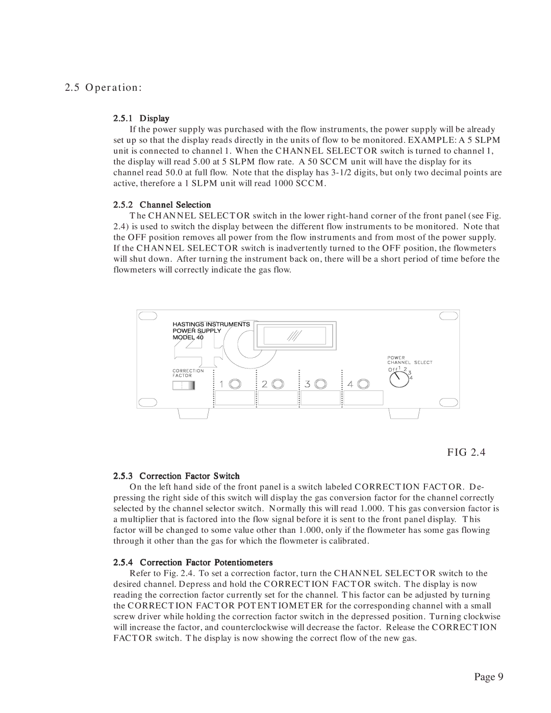
40, Power Supply specifications
Teledyne Power Supply, 40 is a cutting-edge power solution designed to meet the demanding needs of various industries, including aerospace, defense, telecommunications, and industrial applications. This advanced power supply system boasts several key features and technologies that enhance its performance and reliability.One of the primary characteristics of the Teledyne Power Supply, 40 is its robust design, capable of delivering high levels of power density while maintaining compact dimensions. This makes it ideal for applications where space is at a premium, such as in satellite systems and airborne electronics. The unit also employs advanced thermal management techniques, ensuring optimal performance even in challenging environments.
The Teledyne Power Supply, 40 is equipped with modular architecture, allowing users to customize the output voltage and current according to specific application requirements. This flexibility is complemented by a wide input voltage range, which provides compatibility with various power sources, making it suitable for both AC and DC input configurations.
One of the standout features of the Teledyne Power Supply, 40 is its integrated digital control system. This technology enables precise monitoring and control of output parameters, enhancing efficiency and performance. Users can easily configure settings via a user-friendly interface, often accessible through a remote connection. The system supports various communication protocols, facilitating seamless integration into existing control systems.
In terms of safety and reliability, the Teledyne Power Supply, 40 incorporates multiple protection mechanisms, including overvoltage, overcurrent, and thermal shutdown features. These safeguards ensure that both the power supply and the connected loads are protected against adverse conditions during operation.
Additionally, this power supply unit is designed to meet stringent military and aerospace standards, ensuring high levels of performance in harsh environments. Its rugged construction and thorough testing protocols contribute to its reliability, making it a trusted choice for mission-critical applications.
In conclusion, the Teledyne Power Supply, 40 is a sophisticated power management solution that combines flexibility, advanced technology, and reliable performance. Its modular design, precision control systems, and comprehensive safety features make it an ideal choice for demanding applications, setting a benchmark for power supply systems in today’s competitive market. Whether utilized in aerospace, industrial, or telecommunications sectors, the Teledyne Power Supply, 40 consistently delivers the performance and reliability required to meet the needs of modern technological demands.

