Hardware Overview
Component View
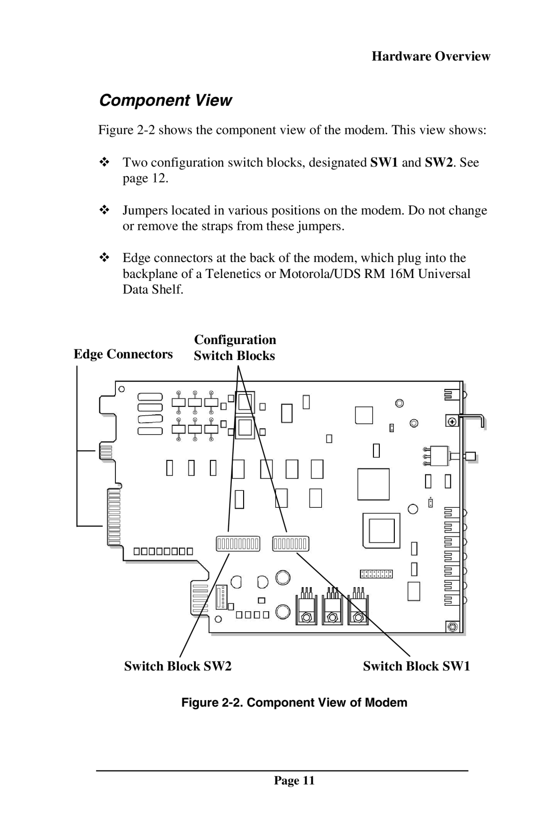
Figure 2-2 shows the component view of the modem. This view shows:
cTwo configuration switch blocks, designated SW1 and SW2. See page 12.
cJumpers located in various positions on the modem. Do not change or remove the straps from these jumpers.
cEdge connectors at the back of the modem, which plug into the backplane of a Telenetics or Motorola/UDS RM 16M Universal Data Shelf.
Configuration
Edge Connectors Switch Blocks
Switch Block SW2 | Switch Block SW1 |
Figure 2-2. Component View of Modem
Page 11