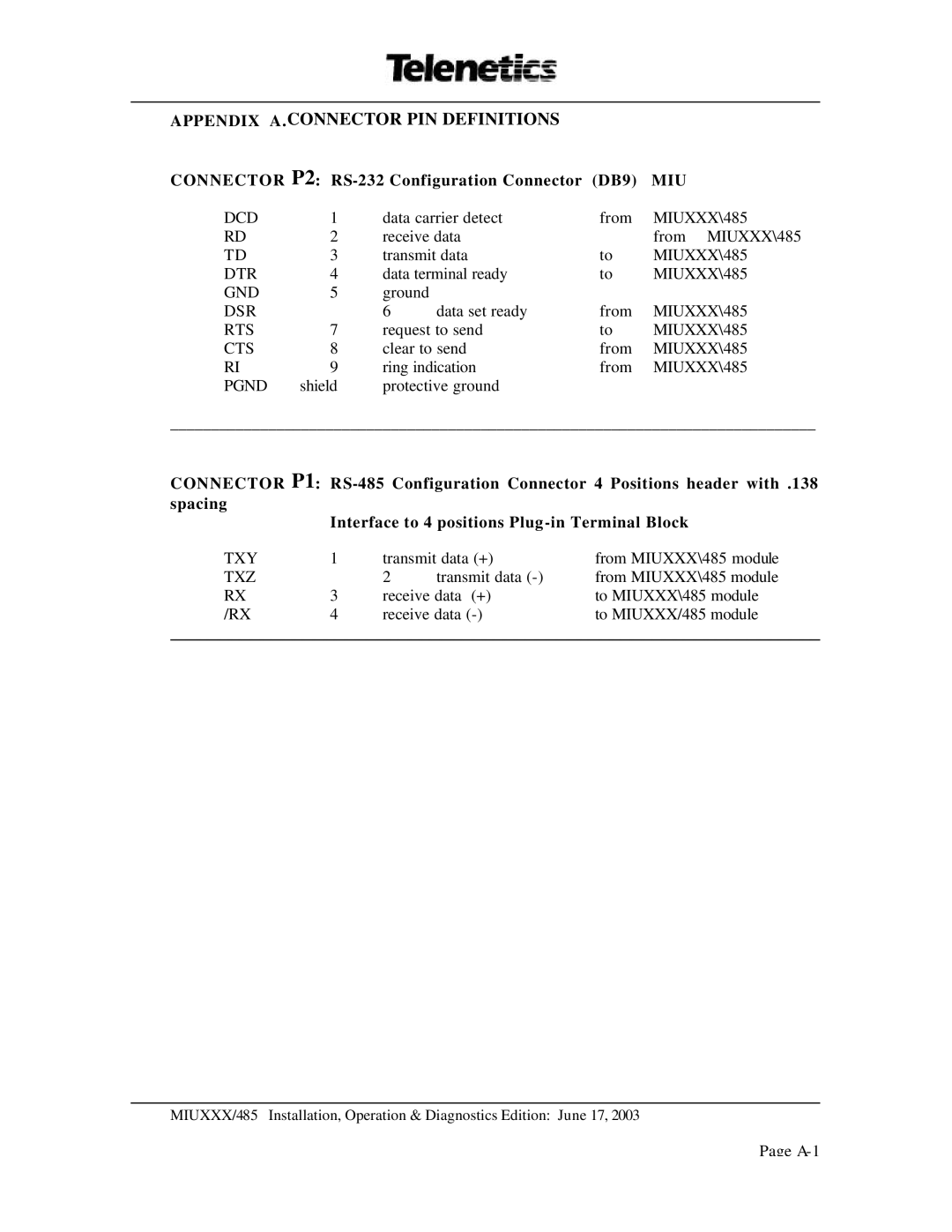
APPENDIX A.CONNECTOR PIN DEFINITIONS
CONNECTOR P2: RS-232 Configuration Connector (DB9) MIU
DCD | 1 | data carrier detect | from | MIUXXX\485 | |
RD | 2 | receive data |
| from MIUXXX\485 | |
TD | 3 | transmit data | to | MIUXXX\485 | |
DTR | 4 | data terminal ready | to | MIUXXX\485 | |
GND | 5 | ground |
|
|
|
DSR |
| 6 | data set ready | from | MIUXXX\485 |
RTS | 7 | request to send | to | MIUXXX\485 | |
CTS | 8 | clear to send | from | MIUXXX\485 | |
RI | 9 | ring indication | from | MIUXXX\485 | |
PGND | shield | protective ground |
|
| |
_______________________________________________________________________________
CONNECTOR P1:
Interface to 4 positions Plug
TXY | 1 | transmit data (+) | from MIUXXX\485 module | |
TXZ |
| 2 | transmit data | from MIUXXX\485 module |
RX | 3 | receive data (+) | to MIUXXX\485 module | |
/RX | 4 | receive data | to MIUXXX/485 module | |
|
|
|
|
|
MIUXXX/485 Installation, Operation & Diagnostics Edition: June 17, 2003
Page
